
Injection applicator for a hypodermic syringe

a technology of hypodermic syringe and applicator, which is applied in the field of injection devices, can solve the problems of not being simple and easy to use, relatively complex and therefore expensive, and not being able to solve the problems of simple and easy use, and achieves the effects of efficient syringe emptying, convenient and accurate filling of the syringe, and minimizing was

Inactive Publication Date: 2006-05-18
COX MICHAEL
View PDF12 Cites 25 Cited by
  • Summary
  • Abstract
  • Description
  • Claims
  • Application Information

AI Technical Summary

Benefits of technology

"The present invention provides an injection applicator that addresses the drawbacks of prior art injection devices. The applicator includes a barrel, a trigger assembly, tension spring means, and stopping means. The trigger assembly includes a locking means that can be unlocked with a force applied to the trigger. The tension spring means applies an axial force to the syringe assembly when the syringe is in a cocked position within the barrel. The injection applicator can also include a filling attachment, an adjustable spacer, a non-adjustable spacer, and a needle guide. The invention provides an improved injection device that is easier to use and more reliable."

Problems solved by technology

However, these devices present one or more of the following disadvantages: are not simple and easy to use, are relatively complex and therefore expensive; require special syringe types, i.e. cannot be used with standard, unmodified, over-the-counter syringes; cannot be aspirated or the syringe contents monitored during the injection process; cannot be used as an aid for filling the syringe from an ampoule; do not permit variation of the dosage or type of medicament; are not re-usable; do not allow for the rate of infusion to be easily varied, monitored or controlled; or cannot be used for deep, intramuscular type injections.

Method used


Image

  • Injection applicator for a hypodermic syringe
  • Injection applicator for a hypodermic syringe
  • Injection applicator for a hypodermic syringe

Examples


Embodiment Construction

[0057] The following description is of a preferred embodiment.

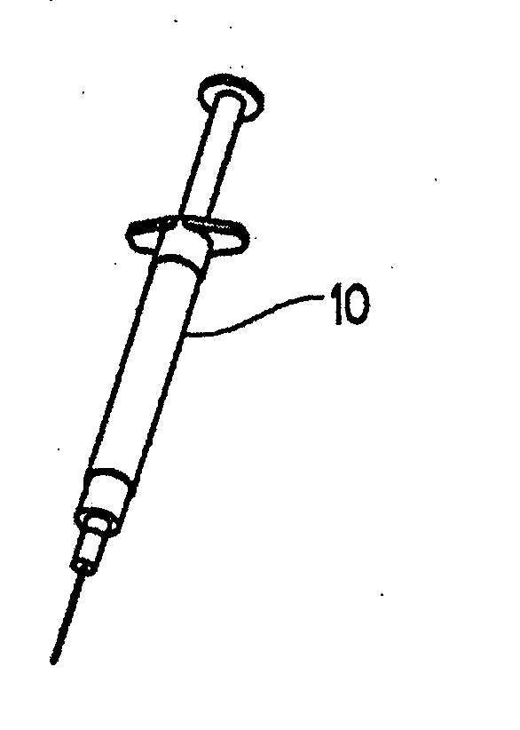
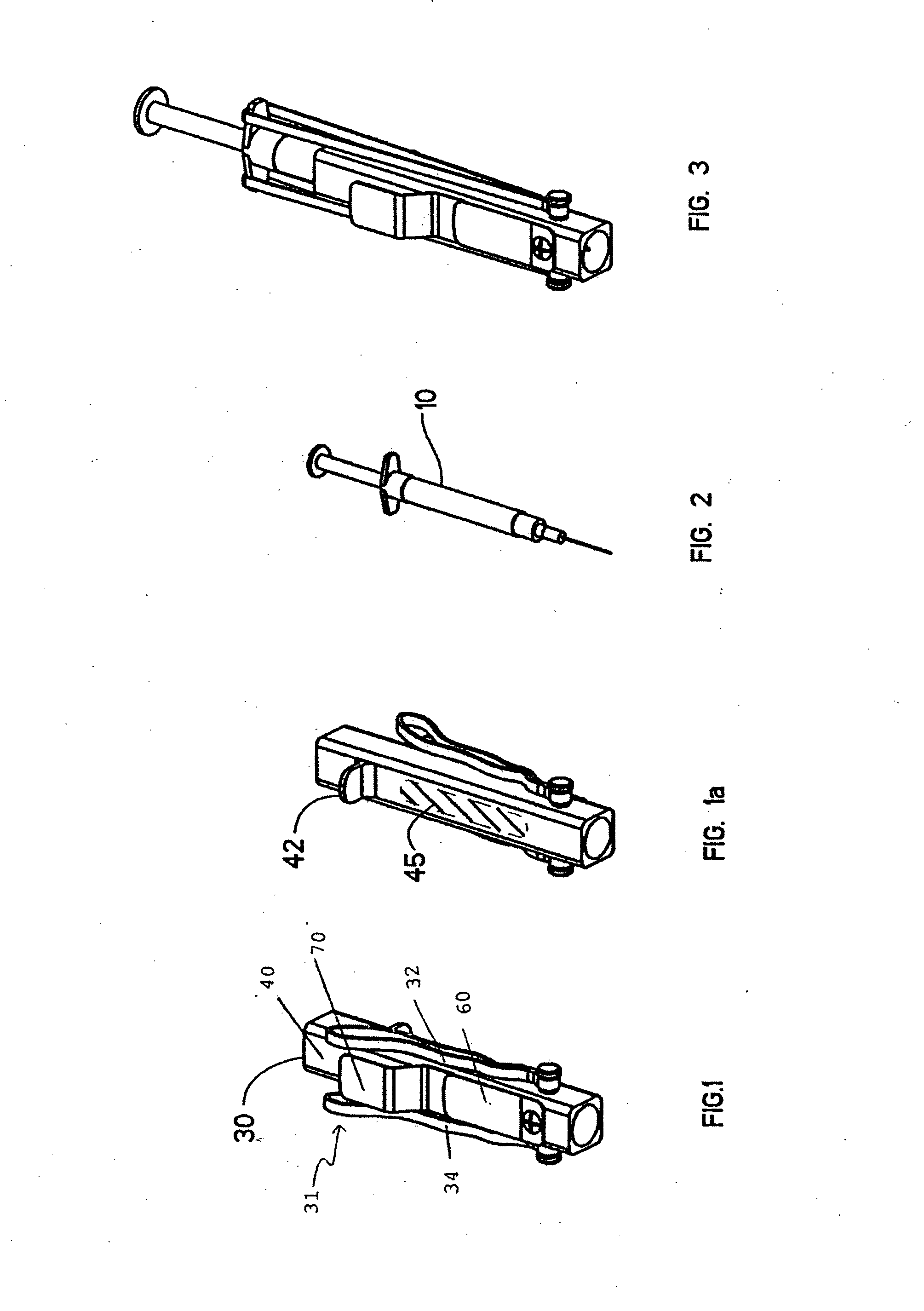
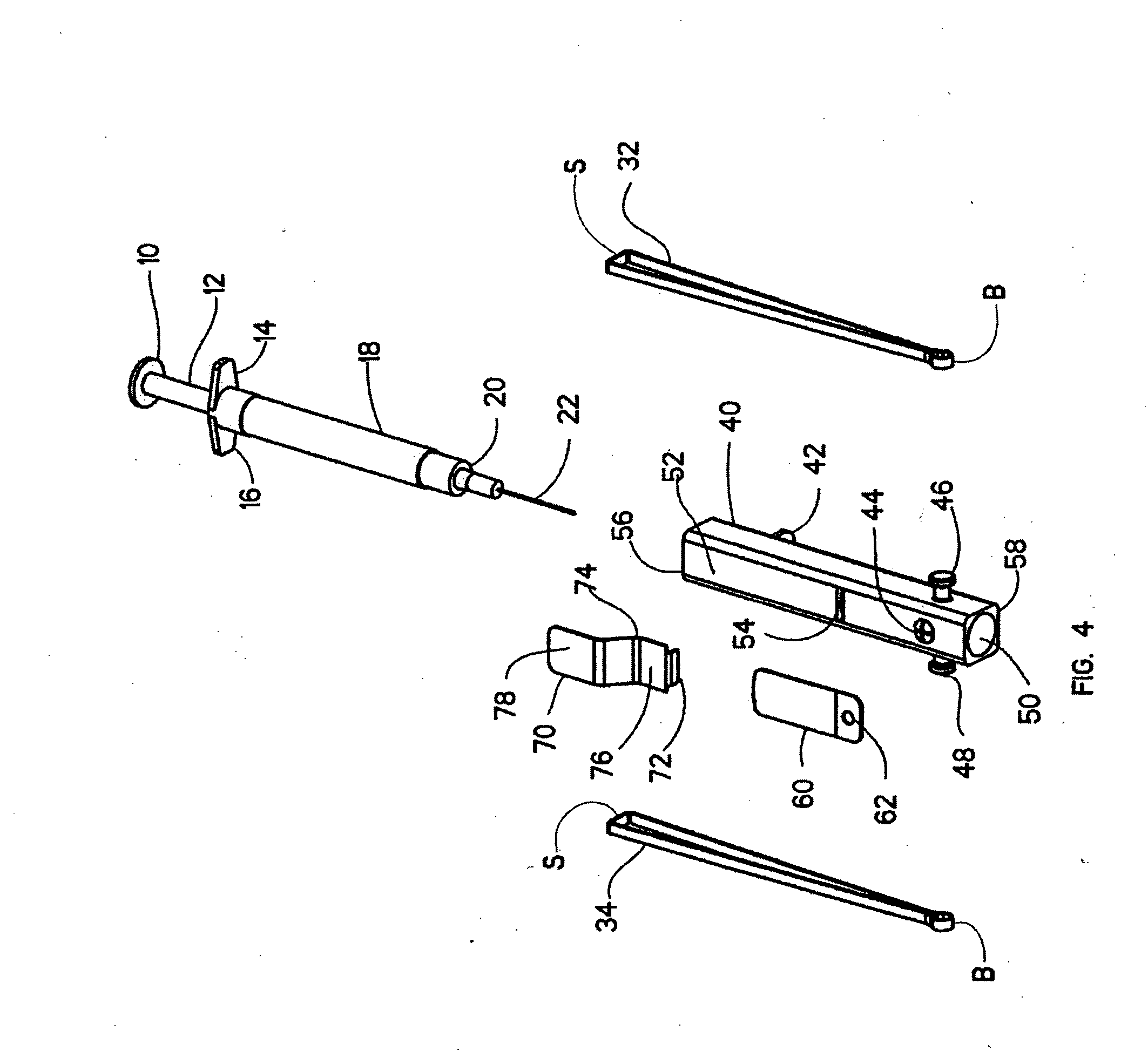
[0058] Referring to the figures, and without wishing to be limiting in any manner, there is provided an injection device or applicator 30 comprising a barrel 40 adapted for receiving a syringe assembly 10, a trigger assembly 70, tension spring means 31 and stopping means 56. The trigger assembly comprises retractable blocking means 72 for blocking the syringe assembly at a first axial point within the barrel and a trigger for retracting said blocking means 72 from blocking the syringe assembly 10 along said first axial point along the barrel 40. The tension spring means 31 have a barrel end B mountable on the barrel and a syringe end S mountable on the syringe assembly 10, whereby said tension spring means 31 impart an axial pulling or pushing force to the syringe assembly 10 when the syringe assembly 10 is in a cocked position. The stopping means 56 are for retaining the syringe assembly in an injected position within t...


PUM


Abstract

There is provided an injection device comprising a barrel adapted for receiving a syringe assembly, a trigger assembly, tension spring means and stopping means. The trigger assembly comprises retractable blocking means for blocking the syringe assembly at a first axial point within the barrel and a trigger for retracting said blocking means from blocking the syringe along said first axial point along the barrel. The tension spring means has a barrel end mountable on the barrel and a syringe end mountable on the syringe assembly, whereby said tension spring means imparts an axial force to the syringe assembly when the syringe assembly is in a cocked position. The stopping means are for retaining the syringe assembly in an injected position within the barrel upon release of the syringe assembly from the cocked position followed by axial travel of the syringe assembly within the barrel under the influence of the axial force.

Description

FIELD OF INVENTION [0001] This invention is directed to injection devices and particularly but not exclusively to an applicator for a hypodermic syringe. BACKGROUND OF THE INVENTION [0002] The requirement for self, or home-administered injections by non-medical personnel is becoming more common. Some of the reasons for this need are increased prescriptions of injectable medicaments including hormones and vitamins. For example, medicaments such as insulin have to be administered frequently and often at irregular times. Also, in many cases a person requiring a injectable medicament may be incapacitated to some degree, for example, in cases of asthma or reactions to such things as allergens, insect stings, venom toxins or the like when an antidote, for example, atropine, adrenaline (epinephrine) or other medicament must be immediately injected. [0003] Various systems have been proposed in the past for assisting with injections such as in those described in U.S. Pat. Nos. 4,787,891, 6,1...

Claims


Application Information

Patent Timeline
Patent Type & Authority Applications(United States)
IPC IPC(8): A61M5/00A61M5/178A61M5/31
CPCA61M5/3287A61M5/46
Inventor COX, MICHAEL
Owner COX MICHAEL
Learn More