Disposable front loadable syringe and injector

a syringe and front-loading technology, which is applied in the field of disposable replacement syringes, can solve the problems of affecting the rapid attachment and replacement of the syringe, affecting the safety of patients, so as to prevent, reduce, or eliminate the risk of fluid leakage, the effect of rapid loading of the syring

Inactive Publication Date: 2006-05-18
MALLINCKRODT INC
View PDF20 Cites 27 Cited by
  • Summary
  • Abstract
  • Description
  • Claims
  • Application Information

AI Technical Summary

Benefits of technology

[0006] The present invention provides injectors, syringe interfaces and syringes that address the needs for rapid loading of syringes and the prevention or elimination of fluid leaks between the syringe nozzle and fluid delivery tubing connection, a Luer lock connection. Specifically, the present invention provides a syringe for an injector that has at its nozzle end a connection to the fluid delivery tubing that prevents, reduces, or eliminates fluid leaks. The syringe can also be oriented in more than one manner on the injector.

Problems solved by technology

Syringes that contain fluid under the higher range of pressures are expensive and therefore can be impractical where the syringes are disposable.
This required orientation hinders rapid attachment and replacement of the syringe.
In addition, although the Luer connection, syringe / tubing connection, described in the above patents may be adequate for injector applications that use low pressures, leaks often occur when high pressure applications are used.
Over-tightened Luer connectors sometimes crack which compromises the seal.
Another problem is that sometimes the connection sticks and the Luer lock cannot be disassembled.

Method used


Image

  • Disposable front loadable syringe and injector
  • Disposable front loadable syringe and injector
  • Disposable front loadable syringe and injector

Examples


Embodiment Construction

[0033] As noted in the Background section, there is a need to more quickly load and unload disposable replacement syringes in injectors. A type of injector for the use of the present invention is described in U.S. Pat. No. 5,300,031; U.S. Pat. No. 5,451,211; and U.S. Pat. No. 5,658,261 which are incorporated by reference herein in their entirety.

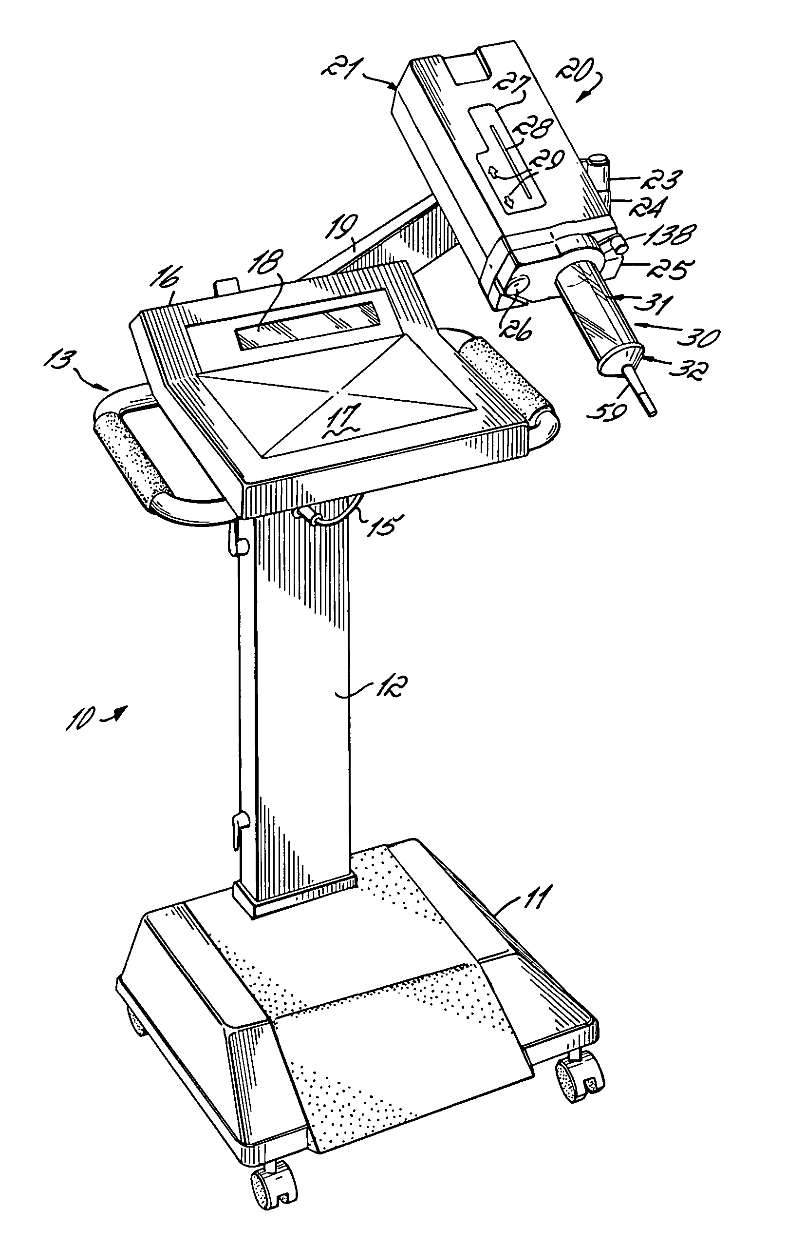
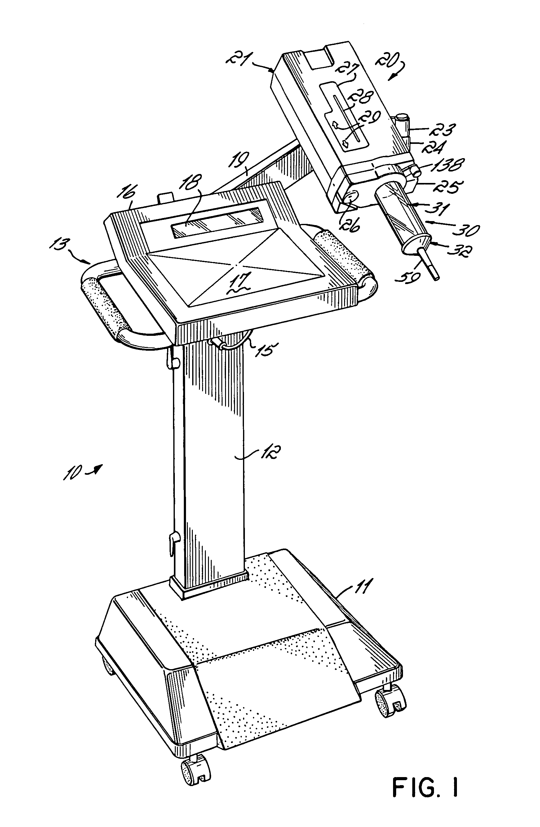
[0034] Briefly, an example of an injector 10 with use of the present invention is illustrated in FIG. 1. The injector 10 includes a wheeled base 11 to the top of which is rigidly supported a vertically adjustable upstanding support column 12. A control module platform 13 is supported at the top of the column 12. Electrical power is communicated from a power cord (not shown) through the base 11 and the upstanding support 12 and through a power lead 15 to a control module 16 rigidly supported to the platform 13. The control module 16 includes a programmable microprocessor (not shown) to which commands and programming codes are input through a...


PUM


Abstract

A syringe for an injector that has at its nozzle end a connection to the fluid delivery tubing that prevents, reduces, or eliminates fluid leaks, by virtue of a ridge on the external surfaces of the connector which engage to tubing. Furthermore, the syringe and injector are configured to permit the syringe to be oriented in more than one manner on the injector.

Description

FIELD OF THE INVENTION [0001] The present invention relates to disposable replacement syringes for patient fluid injectors and adapters for a fluid injector to accept the syringe. BACKGROUND OF THE INVENTION [0002] Injectors are devices that expel fluid, such as contrasting media, from a syringe and through a tube into a patient. The injectors are provided with an injector unit, usually adjustably fixed to a stand or support, having a drive that couples to the plunger of the syringe to drive it forward to expel fluid into the tube, or that may be driven rearward to draw fluid into the syringe to fill it. Usually the syringe is a disposable replacement type. [0003] In the injection phase where the plunger is driven forward, pressures are developed in the syringe that range from, for example, 25 psi for some applications to over 1000 to 1200 psi for other, applications. Syringes that contain fluid under the higher range of pressures are expensive and therefore can be impractical where...

Claims


Application Information

Patent Timeline
Patent Type & Authority Applications(United States)
IPC IPC(8): A61M37/00A61M5/31A61M25/00
CPCA61M5/14546A61M5/14566A61M5/344A61M5/346A61M2005/14553A61M2005/3103
Inventor FAGO, FRANK M.LEWIS, FRANK M.
Owner MALLINCKRODT INC
Why Eureka
Try Eureka