Joint boot

a joint boot and boot body technology, applied in the field of belt-shaped joint boots, can solve the problems of difficult circumferential equalization of the contact pressure of the inner wall portion on the outer housing when tightening and fixing the large-diameter attachment part, and the insufficient sealing properties of the outer housing b>6/b>, so as to achieve superior moldability, reduce the effect of internal wall thickness and effectively prevent the production of sink marks

Inactive Publication Date: 2006-05-25
TOYO TIRE & RUBBER CO LTD
View PDF3 Cites 2 Cited by
  • Summary
  • Abstract
  • Description
  • Claims
  • Application Information

AI Technical Summary

Benefits of technology

[0016] In the joint boot of this invention, it is preferred that the lateral strut walls be linked to the inner wall portion in the intermediate position between a linking part (juncture) at the inner wall portion to the central strut wall and a foot part at the inner wall portion to the outer wall portion. Seeing that a weakest part on both sides of the linking part of the inner wall portion to the central strut wall is the intermediate point between the linking part and the foot part to the outer wall portion, it is more effective for equalization of the contact pressure on the outer housing by the inner wall portions that the inner wall portion should be reinforced in this position so as to be supported by the lateral strut walls.
[0017] In the joint boot of this invention, it is also possible to construct so that a center line in the thickness direction of one of the lateral strut walls, a center line in the thickness direction of the other of the lateral strut walls, and a center line in the thickness direction of the central strut wall intersect at one point, and this intersection point is situated radially outwardly of the outer peripheral face of the large-diameter attachment part. When being formed so that the intersection point of the center lines of the lateral strut walls at the right and left hands and the center line of the central strut wall is situated outwardly of the outer peripheral face of the large-diameter attachment part in this manner, the lateral strut walls will be joined to the outer wall portion in a position circumferentially spaced apart from the joining part of the central strut wall to the outer wall portion. Because of that, it is possible to get around the fact that the central strut wall and the lateral strut walls are joined at one point in the middle area of the outer wall portion, which results in a large wall thickness in the aforementioned middle area, and hence it is possible to more effectively prevent the production of sink marks.
[0018] In the joint boot of this invention, at each of the bulging portions, four relief holes divided by the central strut wall and the pair of lateral strut walls may be juxtaposed in the circumferential direction and formed in a manner subsiding in the axial direction from the opening edge face of the large-diameter attachment part. By such formation of the relief holes subsiding from the opening edge face of the large-diameter attachment part, upon molding of the large-diameter attachment part, cores for shaping the relief holes are easy to demold without being obstructed by the bellows part, and the moldability is thus superior.
[0019] According to this invention, in the joint boot to be attached to an outer housing of a non-circular outer peripheral configuration as is the case with tripod type constant velocity joints, it is possible to equalize the contact pressure the bulging portions exert on the outer housing when the joint boot is tightened and secured in the circumferential direction without impairing the modability, thereby ensuring a high sealing capability.

Problems solved by technology

Where such inwardly bulging portions 104 of the large-diameter attachment part 101 are formed as solid thick-walled portions as illustrated in FIG. 7, the thick-walled portions and thin-walled portions are formed alternately in the circumferential direction of the large-diameter attachment part 101, and consequently, a problem arose in that sufficient sealing properties to the outer housing 6 were difficult to ensure.
For that reason, cores for molding such small relief holes are difficult to demold, so that the problem is encountered that the moldability is impaired.
On the other hand, where the inner wall portion and the outer wall portion are linked by a single strut wall in the circumferential centers of both, as is the technology disclosed in Patent Reference 2 above, the moldability is good, but there is still the problem that the contact pressure the inner wall portions exert on the outer housing when tightening and fixing the large-diameter attachment part is difficult to be equalized in the circumferential direction.

Method used


Image

  • Joint boot
  • Joint boot
  • Joint boot

Examples


Embodiment Construction

[0029] Embodiments for carrying the invention into effect will be described with reference to the accompanying drawings.

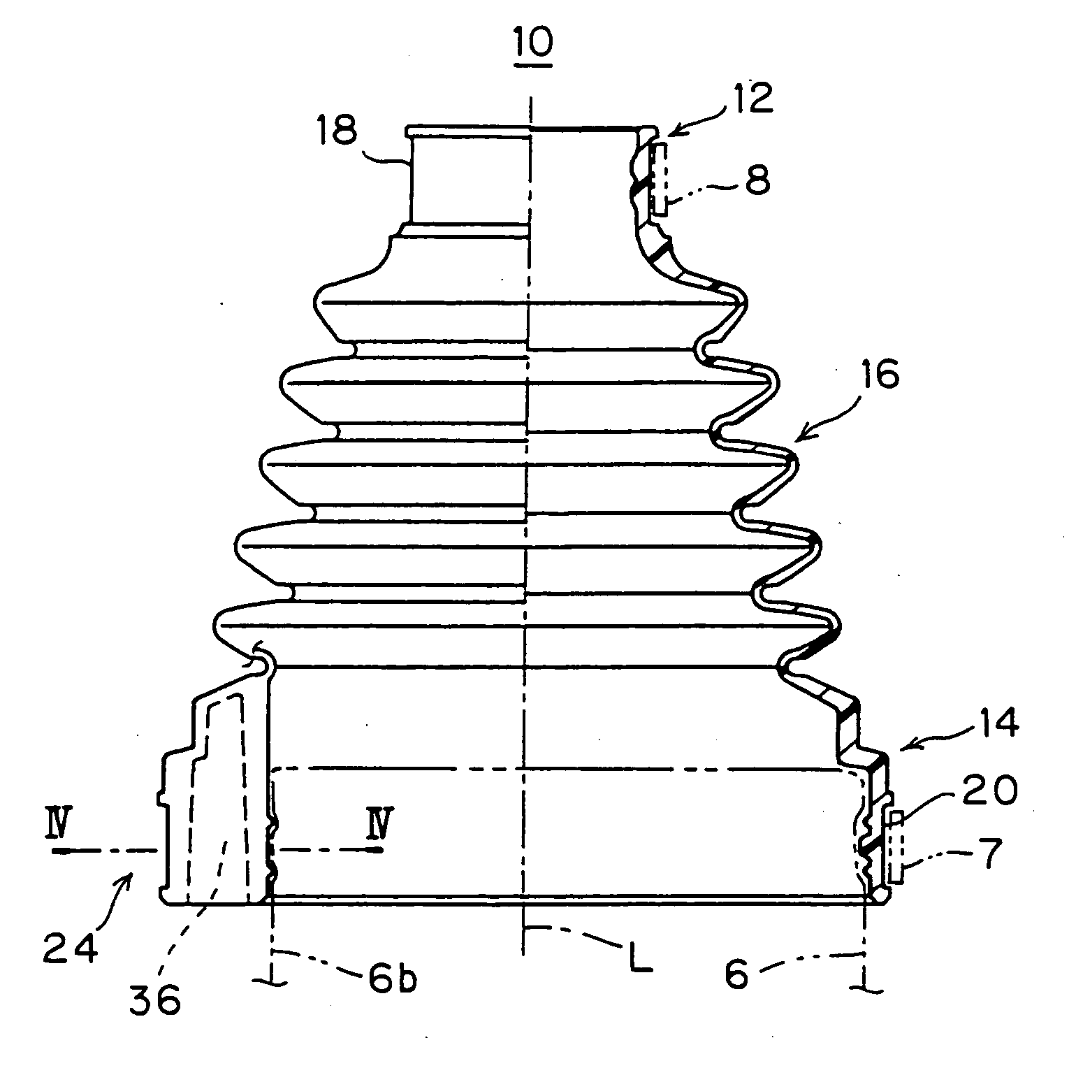
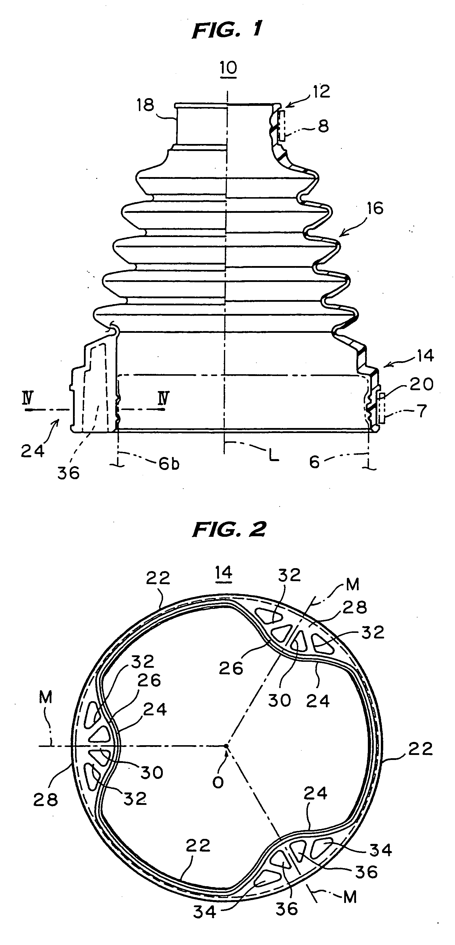
[0030]FIG. 1 is a half sectional, half side elevational view of a joint boot 10 relating to one embodiment of this invention, and FIG. 2 is a front elevation of its large-diameter side. The joint boot 10 is a boot made of thermoplastic elastomer resin destined to be mounted on a tripod type constant velocity joint for automobiles illustrated in FIGS. 7 and 8 as stated above. The joint boot 10 includes a small-diameter attachment part 12 at its one end, a large-diameter attachment part 14 at the other end disposed coaxially with the small-diameter attachment part 12 to be spaced apart from it, and a bellows part 16 of a hollow form integrally joining the small-diameter attachment part 12 and the large-diameter attachment part 14, and is fabricated integrally by a conventional molding method such as injection blow molding.

[0031] The small-diameter attachment part 1...


PUM


Abstract

In a joint boot to be mounted on an outer housing having a non-circular outer peripheral configuration, the invention is designed for ensuring a high sealing capability without impairing the moldability. To that end, its large-diameter attachment part to be attached to the outer housing is configured, in its internal peripheral contour, to bulge radially inwardly in plural circumferential places thereof so that bulging portions each include an inner wall portion radially inwardly bulging in a curved form, an arc-like outer wall portion constituting part of an outer peripheral face of the large-diameter attachment part, a radially extending central strut wall linking these inner and outer wall portions in peripheral centers of both, and lateral strut walls linking on both sides of the central strut wall the inner and outer wall portions. The lateral strut walls are slanted such that their outward parts approach the central strut wall.

Description

BACKGROUND OF THE INVENTION [0001] 1. Field of the Invention [0002] This invention relates to a bellows-shaped joint boot mainly used for tripod type constant velocity joints or the like of automobiles. [0003] 2. Description of Related Art [0004] As one of constant velocity joints for use in a driveshaft, etc. of vehicles, a tripod type joint is well known. [0005] A tripod type constant velocity joint is, as shown in FIGS. 7, 8 by way of example, comprised of a tripod 4 wherein three trunnions 3 having respective rollers 2 are provided at the one shaft 1 of input and output side shafts in a manner projecting in a normal direction to the axis thereof, and an outer housing 6 provided at an end of the other shaft 5. The outer housing 6 has on its inner periphery three axial grooves 6a for sliding corresponding to the tripod 4. The constant velocity joint is constructed so that the rollers 2 of the tripod 4 are fitted to be axially slidable in the sliding grooves 6a, thereby enabling th...

Claims


Application Information

Patent Timeline
Patent Type & Authority Applications(United States)
IPC IPC(8): E04B1/00
CPCF16D3/845F16J3/042F16D3/2055
Inventor OHSHITA, TAKENORI
Owner TOYO TIRE & RUBBER CO LTD
Why Eureka
Try Eureka