

Refrigerant cycle device for vehicle
a technology vehicle, which is applied in the direction of machine operation, lighting and heating apparatus, transportation and packaging, etc., can solve the problems of deteriorating mounting inability to effectively improve the cooling performance of refrigerant cycle device, and difficulty in suitably adjusting the flow amount of refrigerant into each of the first and second evaporators. to achieve the effect of improving the cooling performan
- Summary
- Abstract
- Description
- Claims
- Application Information
AI Technical Summary
Benefits of technology
Problems solved by technology
Method used
Image

Examples
first embodiment
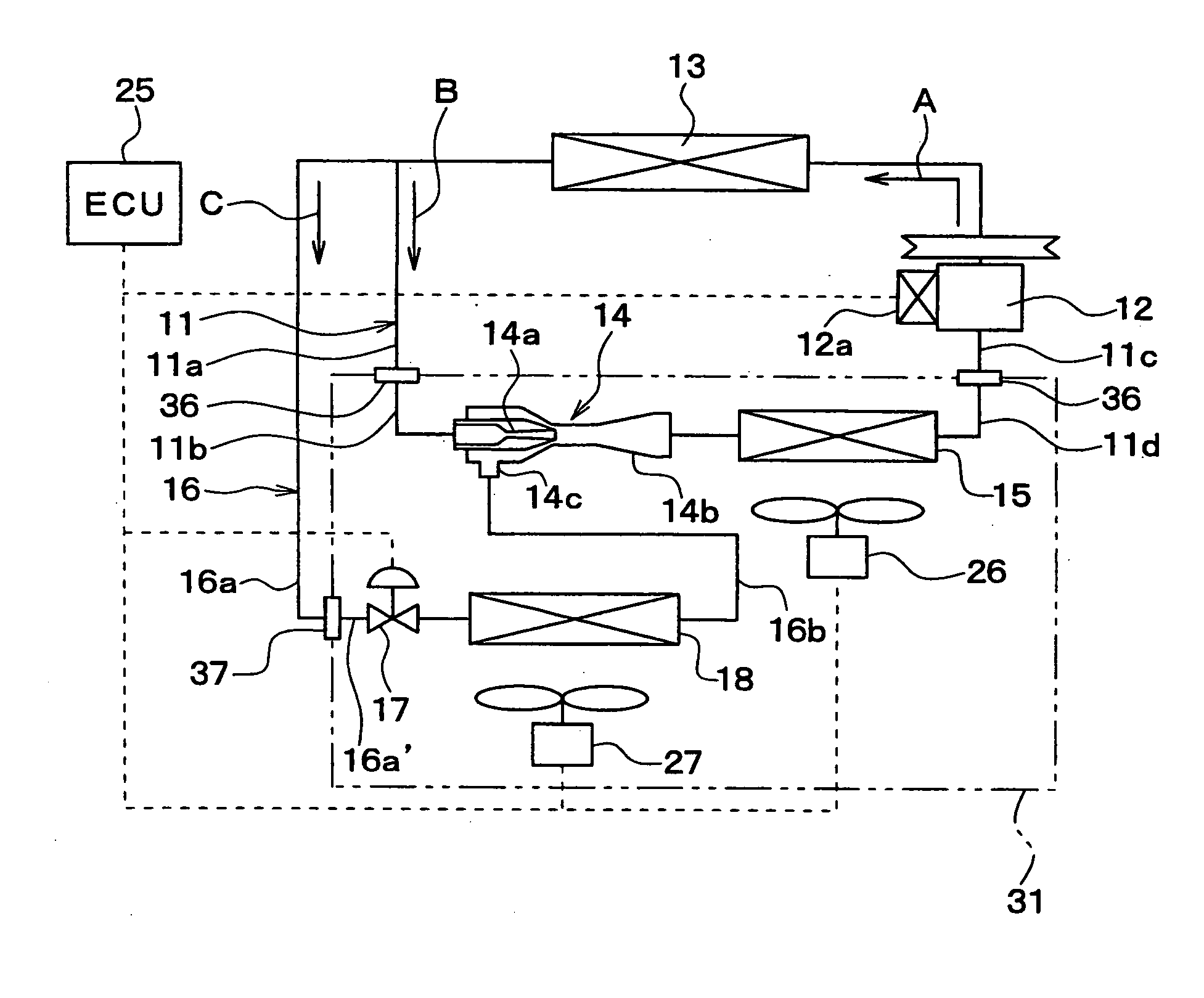
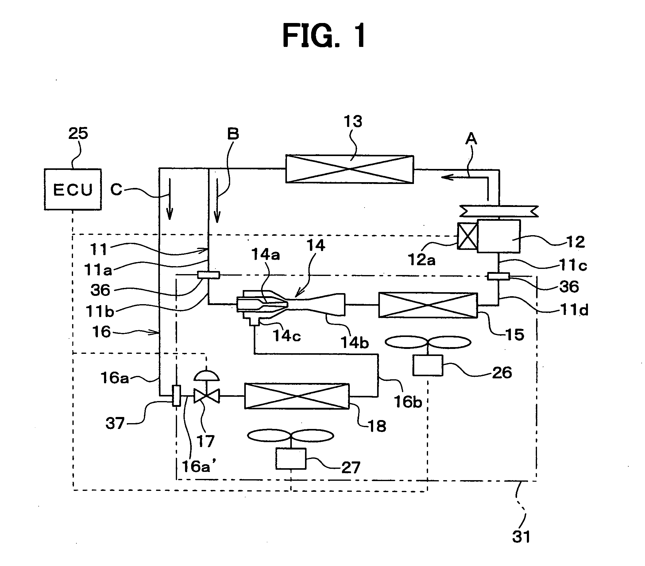
[0024] In the first embodiment, a vapor-compression refrigerant cycle device having an ejector, shown in FIG. 1, is typically used for a vehicle air conditioner, as an example. The refrigerant cycle device includes a refrigerant circulating path 11 in which refrigerant flows in this order of a discharge side of a compressor 12, a refrigerant radiator 13, an ejector 14, a first evaporator 15 and a suction side of the compressor 12.
[0025] In this embodiment, the compressor 12 for compressing refrigerant is driven and rotated by a vehicle engine through a belt. The compressor 12 is a variable displacement compressor in which a refrigerant discharge capacity can be adjusted by adjusting its displacement. For example, the displacement is a refrigerant amount discharged from the compressor 12 in per rotation. As the variable displacement compressor 12, a swash-plate type compressor can be used. In this case, a pressure (i.e., control pressure) in a swash chamber is changed by an electrom...
second embodiment
[0071] The second embodiment will be now described with reference to FIGS. 4 and 5. FIG. 4 is a schematic diagram showing a refrigerant cycle device of the second embodiment, and FIG. 5 is a schematic diagram showing a mounting state of the refrigerant cycle device in the vehicle according to the second embodiment. In the second embodiment, a third evaporator 22 is added in addition to the first and second evaporators 15, 18 of the first embodiment.
[0072] In the second embodiment, the branch passage 16 in the above-described first embodiment is used as a first branch passage 16. Furthermore, a second branch passage 23 is provided to be branched from the first branch passage 16 at an upstream side position of the throttle mechanism 17 and to be joined to a refrigerant outlet side of the first evaporator 15. That is, the second branch passage 23 is branched from the first branch passage 16 at a refrigerant upstream side of the throttle mechanism 17 and is joined to the refrigerant ci...
third embodiment
[0079] The third embodiment of the present invention will be now described with reference to FIG. 6.
[0080] In the above-described first and second embodiments, the ejector 14 and the first evaporator 15 are connected in series, so that the ejector 14 has a flow adjusting function for adjusting a flow amount of refrigerant flowing into the first evaporator 15, and a pumping function with a refrigerant pressure difference between the first evaporator 15 and the second evaporator 18. In this case, the elector 14 is need to be designed in accordance with the cooling function of the first evaporator 15, thereby it is difficult to operate the refrigerant cycle having the ejector 14 with a high efficiency.
[0081] In the third embodiment, the ejector 14 is used to have only pumping function, and a throttle mechanism 39 is provided in the refrigerant circulating path 11 for adjusting the flow amount of refrigerant flowing into the first evaporator 15. In this case, the structure of the ejec...
PUM
 Abstract
Description
Claims
Application Information