
Automatic pressure control device for quartz tube

Inactive Publication Date: 2006-05-25
SAMSUNG ELECTRONICS CO LTD
View PDF2 Cites 3 Cited by
  • Summary
  • Abstract
  • Description
  • Claims
  • Application Information

AI Technical Summary

Benefits of technology

[0013] Accordingly, the present invention has been made to solve the above-mentioned problems occurring in the prior art and provides additional advantages, by providing an automatic pressure control device capable of detecting and automatically controlling gas pressure within a quartz tube, thus improving the quality of the resulting preform.
[0014] One aspect of the present invention is to provide an automatic pressure control device capable of detecting and automatically controlling gas pressure within a quartz tube and for stabilizing the feed of gas into the quartz tube.

Problems solved by technology

However, the discharge tube may become clogged with soot when the gas pressure inside the quartz tube is changed due to an external factor during the MCVD process.
If the process is continued under such an unstable condition, there will be a great change in the amount of nitrogen gas fed into the nitrogen tube, as well as in the pressure and gas stream within the quartz tube, thereby deteriorating the preform deposition quality.

Method used


Image

  • Automatic pressure control device for quartz tube
  • Automatic pressure control device for quartz tube
  • Automatic pressure control device for quartz tube

Examples


Embodiment Construction

[0021] Hereinafter, an embodiment of the present invention will be described with reference to the accompanying drawings. For the purposes of clarity and simplicity, a detailed description of known functions and configurations incorporated herein will be omitted as it may make the subject matter of the present invention unclear.

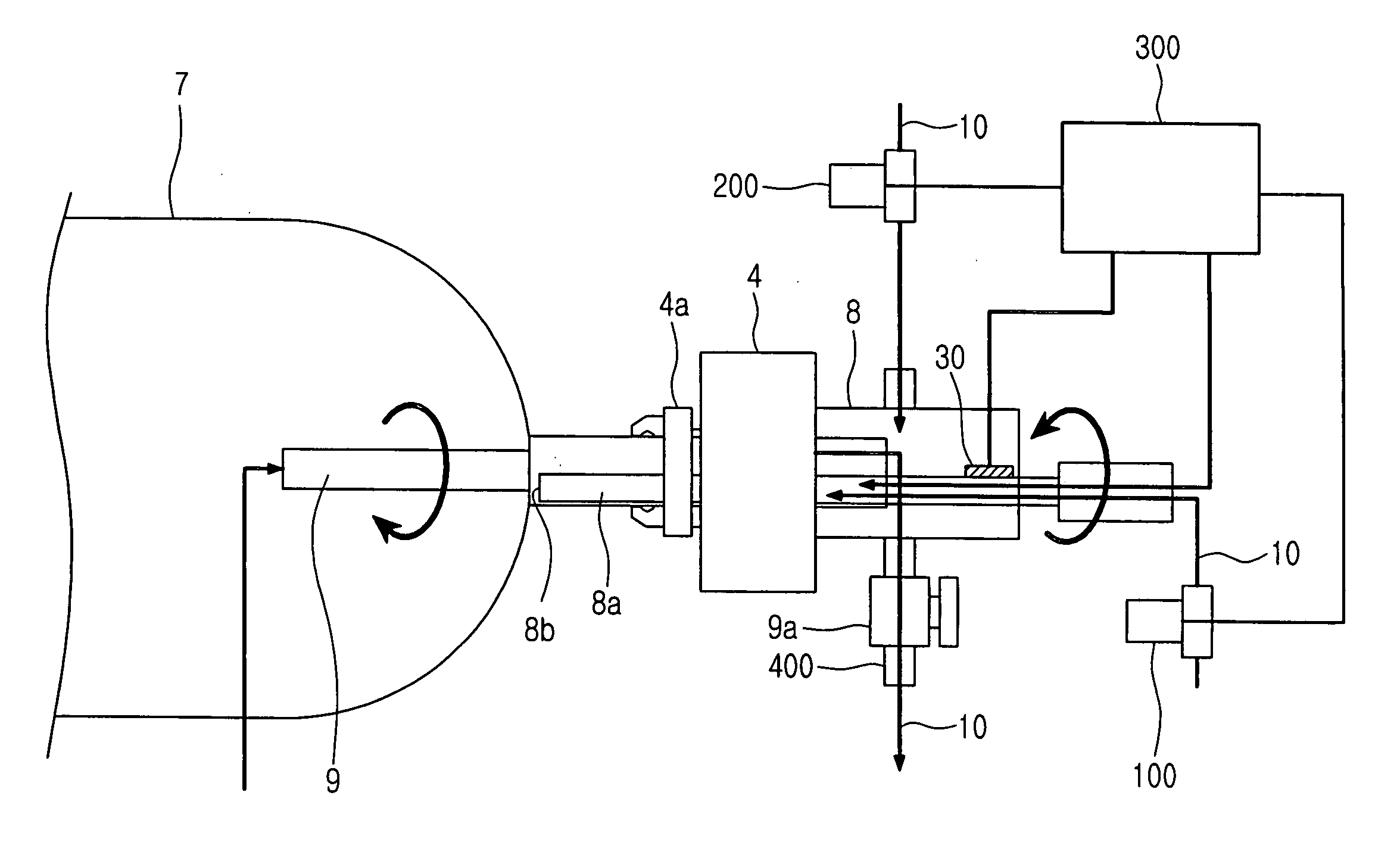
[0022] Referring to FIG. 3, the automatic pressure control device according to the present invention includes a main flow controller 100, a sub flow controller 200, and a gas pressure controller 300. A soot box 8 is coupled to one end of a quartz tube 7 in order to feed and discharge nitrogen gas 10 into and from the quartz tube 7. The soot box 8 has a chuck 4a that holds one end of the quartz tube 7. The main flow controller 100 is connected to the soot box 8 to control the flow rate of the gas 10 fed into the quartz tube 7 in accordance with a preset pressure value. The sub flow controller 200 is also coupled to the soot box 8 to control the flow rate of t...


PUM

PropertyMeasurementUnit
Pressureaaaaaaaaaa

Abstract

An automatic pressure control device for detecting and automatically controlling a gas pressure within a quartz tube in an optical fiber preform fabricating apparatus by regulating the flow rate of gas fed into the quartz tube in accordance with a preset pressure value is disclosed. The automatic pressure control device includes: a main flow controller coupled to a soot box to feed the gas into the quartz tube in accordance with the preset pressure value; a sub flow controller coupled to the soot box to feed the gas into the quartz tube to maintain the preset pressure value when there is a pressure change within the soot box; and a gas pressure controller having a pressure sensor inserted into the soot box to compare a pressure value of a signal detected in real time by the pressure sensor with the preset pressure value and to control the flow rate of the gas to maintain a constant level of gas pressure within the soot box.

Description

CLAIM OF PRIORITY [0001] This application claims priority to an application entitled “Automatic Pressure Control Device for Quartz Tube,” filed with the Korean Intellectual Property Office on Nov. 24, 2004 and assigned Serial No. 2004-97127, the contents of which are hereby incorporated by reference. BACKGROUND OF THE INVENTION [0002] 1. Field of the Invention [0003] The present invention relates to an automatic pressure control device for controlling gas pressure within a quartz tube automatically. [0004] 2. Description of the Related Art [0005] In general, fabrication of optical fibers involves a production of an optical fiber preform. There are several methods used to prepare the optical fiber preforms, namely an outside vapor deposition (OVD), a vapor-phase axial deposition (VAD), and a modified chemical vapor deposition (MCVD). [0006] In the OVD, a rotating target rod (an alumina mandrel) is heated with a burner's hot flame. The burner feeds chemicals to be deposited on the out...

Claims


Application Information

Patent Timeline
IPC IPC(8): C03B37/07
CPCC03B37/01807C03B37/01846G02B6/02Y02P40/57
Inventor KIM, HAK-SEONLEE, YEONG-SEOP
Owner SAMSUNG ELECTRONICS CO LTD
Features
  • Generate Ideas
  • Intellectual Property
  • Life Sciences
  • Materials
  • Tech Scout
  • Unparalleled Data Quality
  • Higher Quality Content
  • 60% Fewer Hallucinations
Learn More