Method and system for monitoring the functional capability of a particle detector

a particle detector and functional capability technology, applied in the direction of electrical control, exhaust treatment electric control, instruments, etc., can solve problems such as proper operation

Inactive Publication Date: 2006-05-25
ROBERT BOSCH GMBH
View PDF9 Cites 13 Cited by
  • Summary
  • Abstract
  • Description
  • Claims
  • Application Information

AI Technical Summary

Problems solved by technology

This is true particularly since the charges or charge shifts to be detected are very small, and interference can incorrectly lead to a finding of proper operation.

Method used


Image

  • Method and system for monitoring the functional capability of a particle detector
  • Method and system for monitoring the functional capability of a particle detector

Examples


Embodiment Construction

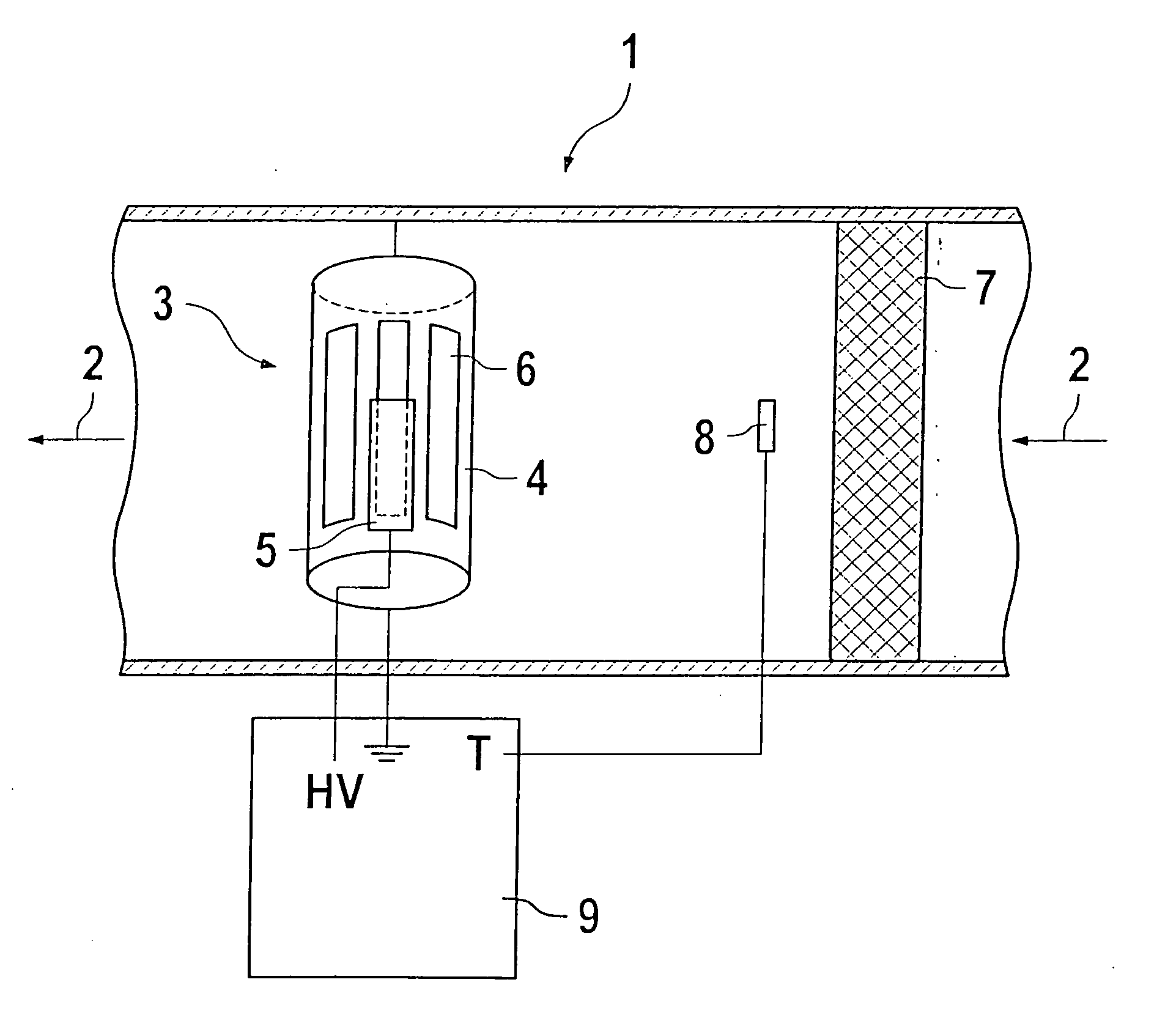
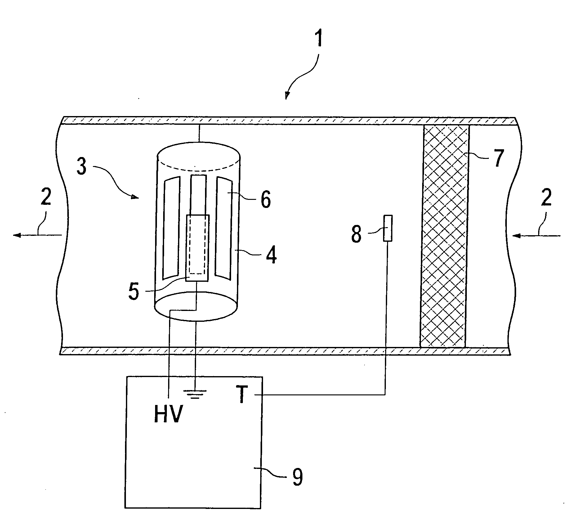
[0021] The present invention will be described taking as an example a soot detector 3 and a soot filter 7, which are located in an exhaust gas line 1 of a diesel engine. The drawing shows the flow direction 2 of the exhaust gas in the exhaust gas line 1, the soot filter 7, and the downstream soot detector 3.

[0022] The soot detector 3 has a first electrode 5, which is connected to a high-voltage source HV via a line. The second electrode 4 of the soot detector 13 is embodied cylindrically and is connected to ground. The first electrode 5 and second electrode 4 are located coaxially to one another. The second electrode 4 has axial recesses 6, through which exhaust gas can flow. With the electrode assembly shown, an ion current can be measured that occurs from the arrival of charged particles at the electrodes 4 and 5. To that end, the ground line and the high-voltage line are carried into a control and evaluation unit 9, in which the further processing of the signals then takes place...


PUM

PropertyMeasurementUnit
temperatureaaaaaaaaaa
temperaturesaaaaaaaaaa

Abstract

A method and a system for monitoring the functional capability of a particle detector connected downstream, in the flow direction, of a particle filter, in which particles occurring upon the regeneration of the particle filter, in particular ions, are detected by the particle detector and the resultant measurement finding are compared with an expected finding. The measurement and evaluation are effected in a control and evaluation unit. The invention enables monitoring of the functional capability of a particle detector that does not interrupt normal operation and thus increases the reliability of the entire system.

Description

[0001] The invention relates to a method and a system for monitoring the functional capability of a particle detector, using a particle filter connected upstream, in the flow direction, of the particle detector. The invention also relates to a computer program (computer program product) suitable for this. PRIOR ART [0002] The concentration of particles, in particular soot particles, in diesel internal combustion engines is often measured by electrical methods. From German Patent Disclosure DE 198 53 584 A1, for instance, a sensor for detecting soot particles is known which includes a first high-voltage electrode and a second ground electrode. In operation, there is a flow of exhaust gas through the space between the electrodes, and either the electrical voltage beyond which sparks occur between the two electrodes, or, if the electrical voltage is kept constant, the magnitude of the ionization current flowing between the two electrodes is used as a standard for the concentration of s...

Claims


Application Information

Patent Timeline
Patent Type & Authority Applications(United States)
IPC IPC(8): G01N33/00F01N3/023F01N11/00G01N15/00G01N15/06
CPCF01N3/023F01N11/002F01N2550/04F01N2560/05F02D41/1466Y10T436/101666G01N15/0618G01N15/0656G01N2015/0046Y02T10/40Y02T10/47F02D41/222
Inventor SCHUMANN, BERND
Owner ROBERT BOSCH GMBH
Why Eureka
Try Eureka