
Sensor-mounted roller bearing apparatus

a technology of roller bearings and roller bearings, which is applied in the direction of force sensors, instruments, force/torque/work measurement apparatus, etc., can solve the problems of difficult structure of the prior art apparatus, difficult to reduce the number of parts and simplify the structure, and easy deformation of the mounting flange, etc., to achieve high accuracy

Active Publication Date: 2006-05-25
JTEKT CORP
View PDF7 Cites 19 Cited by
  • Summary
  • Abstract
  • Description
  • Claims
  • Application Information

AI Technical Summary

Benefits of technology

The present invention provides a sensor-mounted roller bearing apparatus that allows for accurate load detection using a smaller number of parts and has a simplified structure. The apparatus includes a fixed bearing ring, a rotary bearing ring, and rolling elements rollably provided between the bearing rings. The apparatus includes piezoelectric elements interposed between the fixed bearing ring and a fixing part to detect loads applied between the fixed bearing ring and the fixing part. The piezoelectric elements are interposed in the axial and radial directions of the bearing to detect both axial and radial loads. The load sensors are provided on a fixing means that fixes the fixed bearing ring and the fixing part to detect loads in the longitudinal, vertical, and transverse directions of a vehicle. The apparatus simplifies the detection of loads and reduces the number of parts.

Problems solved by technology

Consequently, it is difficult in this prior art apparatus to reduce the number of parts and simplify the structure.
A radio transmitter or a slip ring must be provided to output detection signals from the strain gauges to a control apparatus, which complicates the structure of the bearing apparatus.
In this prior art bearing apparatus, through-holes are formed in the mounting flange and the strain gauges are attached to the surface of the through-holes so that the mounting flange is easily deformed (distorted) for accurate load detection, hampering attempts to simplify the assembly of the load sensor.

Method used


Image

  • Sensor-mounted roller bearing apparatus
  • Sensor-mounted roller bearing apparatus
  • Sensor-mounted roller bearing apparatus

Examples


Embodiment Construction

[0030] Preferred embodiments of the sensor-mounted roller bearing apparatus (occasionally simply referred to bearing apparatus hereafter) of the present invention are described hereafter with reference to the drawings. In the following explanation, the present invention is applied to a driven wheel hub unit of a vehicle by way of example.

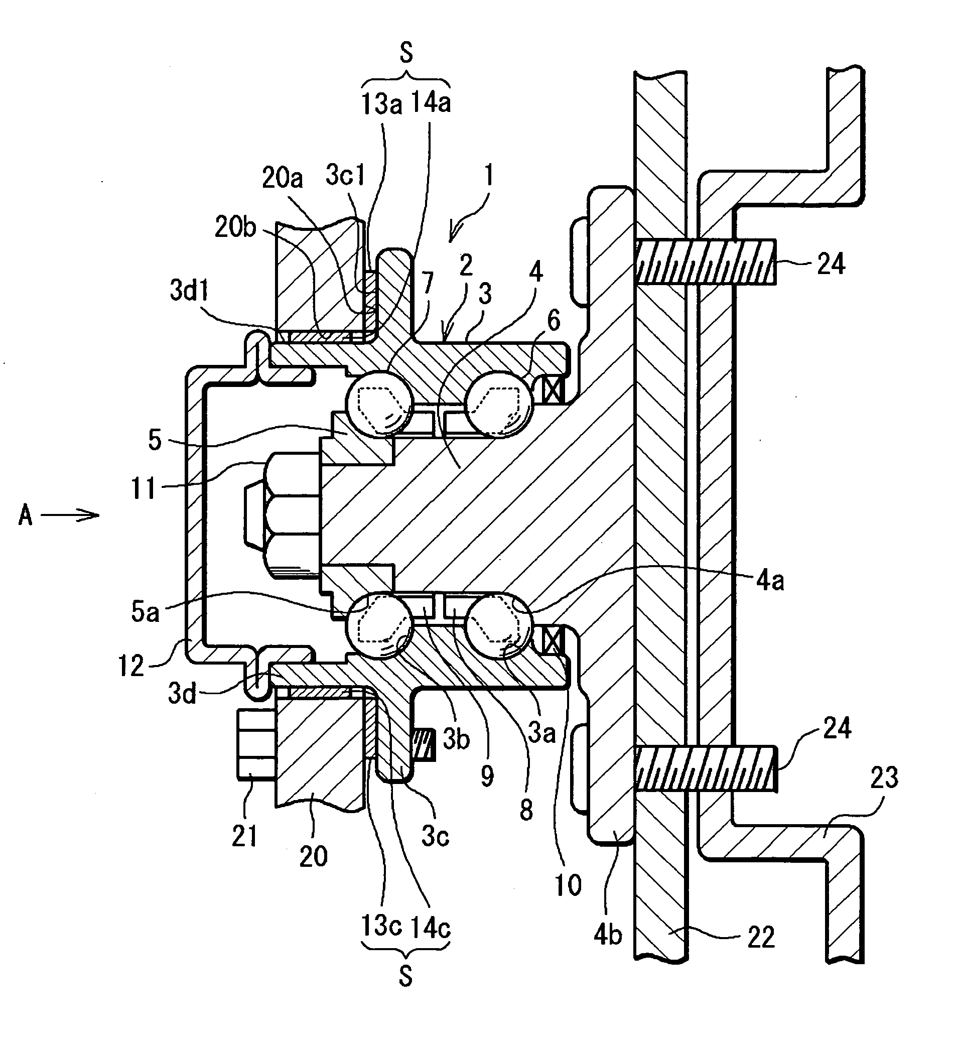
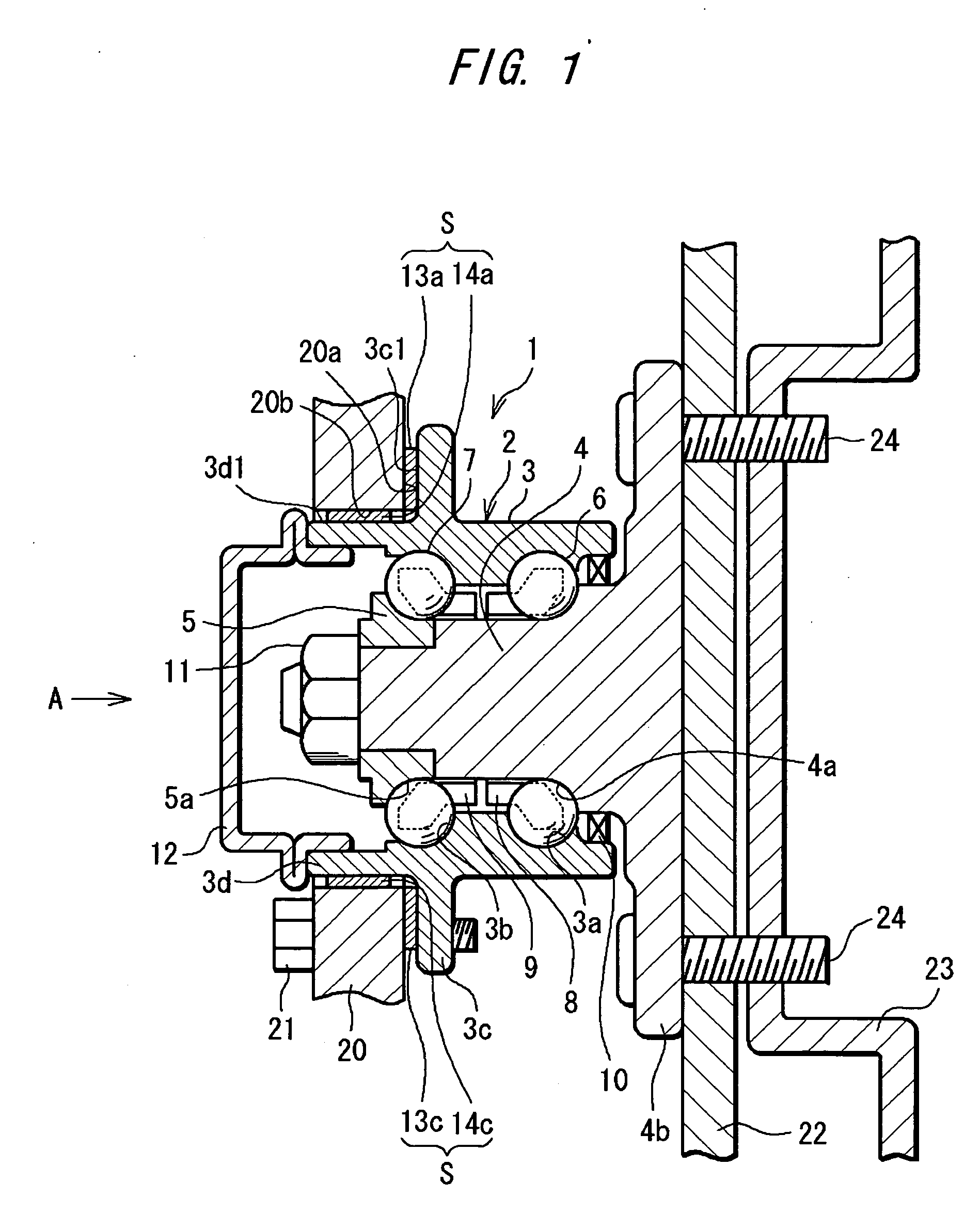
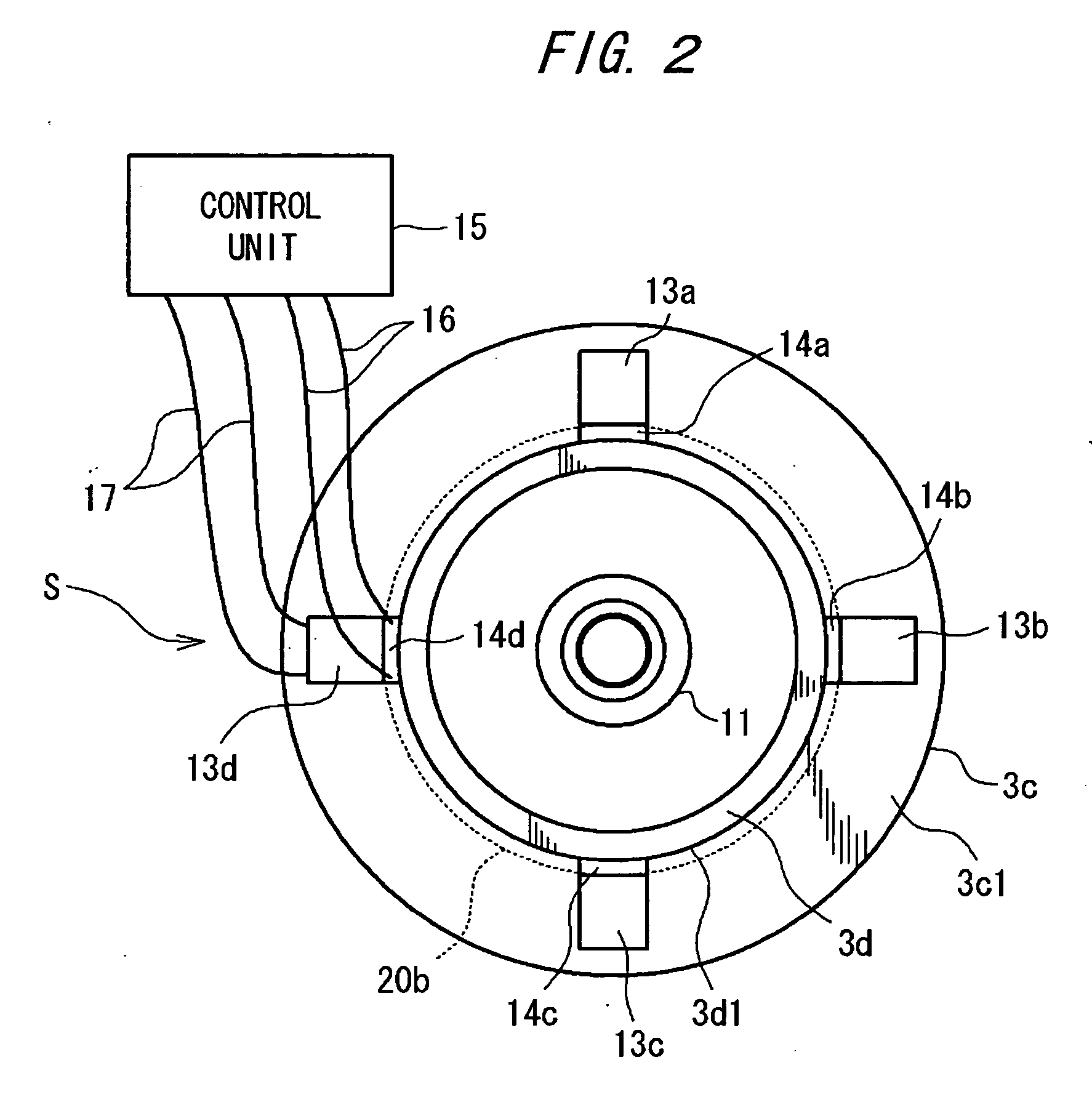
[0031]FIG. 1 is a cross-sectional view of an embodiment of the bearing apparatus according to the first aspect of the present invention. FIG. 1 shows the outer side (wheel side) of the vehicle to the right and the inner side of the vehicle to the left. A bearing apparatus 1 of this embodiment is composed of a roller bearing apparatus 2 and a sensor device S. The roller bearing apparatus 2 is of a double-row angular ball bearing type and comprises an outer ring 3, an inner shaft (hub) 4, an inner ring 5, and rolling elements, or multiple balls, 6 and 7. The roller bearing apparatus 2 also comprises cages 8 and 9 that hold the rolling elements 6 and ...


PUM

PropertyMeasurementUnit
thicknessaaaaaaaaaa
thicknessaaaaaaaaaa
flexuralaaaaaaaaaa

Abstract

A roller bearing apparatus having a fixed bearing ring, a rotary bearing ring, and rolling elements rollably provided between the bearing rings. Piezoelectric elements are provided in the form of a film interposed between the fixed bearing ring and a fixing part to which the fixed bearing ring is fixed so as to detect loads applied between the fixed bearing ring and the fixing part.

Description

BACKGROUND OF THE INVENTION [0001] The present invention relates to a sensor-mounted roller bearing apparatus in which sensors are installed. [0002] Among roller bearing apparatus, sensor-mounted roller bearing apparatus are provided with sensors for detecting operation data such as loads in the course of bearing rotation besides their original bearing function. For example, Japanese Patent Publication of No. 2003-530565 describes a bearing apparatus applied to the bearing hub unit of a vehicle in which multiple sensor modules having strain gauges attached to the surface of a housing surrounding a bearing ring are provided and loads are detected based on the sensing results from the modules. Japanese Unexamined Patent Application No. 2003-246201 describes a bearing apparatus applied to the bearing hub unit of a vehicle in which strain gauges are attached to the mounting flange of an inner ring (a rotary bearing ring) to detect loads applied to the bearing apparatus. [0003] The beari...

Claims


Application Information

Patent Timeline
Patent Type & Authority Applications(United States)
IPC IPC(8): G01L3/14
CPCB60G2204/115G01L5/0009G01L5/0019F16C35/077F16C19/186F16C19/522F16C2326/02
Inventor SENTOKU, MINORU
Owner JTEKT CORP
Learn More