Sawing device and its safety system for precaution of a breaking saw chain

a safety system and sawing device technology, applied in the field of forest machines, can solve the problem of not being able to completely encapsulate the saw box, and achieve the effects of preventing the back-and-forth movement of the saw box, preventing the loosening of the parts of the saw chain, and controlling the behaviour of the saw chain

Active Publication Date: 2006-05-25
JOHN DEERE FORESTRY OY
View PDF16 Cites 8 Cited by
  • Summary
  • Abstract
  • Description
  • Claims
  • Application Information

AI Technical Summary

Benefits of technology

[0010] It is an advantage of the invention to prevent the back-and-forth movement of the saw chain. By means of the walls of the saw box frame it is not possible to prevent the generation of the whip-like movement, wherein loosening of parts and occurrence of flying parts is possible. It is not possible to encapsulate the saw box entirely, because sawdust must have access away from the vicinity of the saw box and out of the saw box. Furthermore, the saw box must be sufficiently open so that both maintenance and sawing would be possible. When the shielding of the saw box is increased, the loosening of the parts of the saw chain is not prevented entirely, wherein the danger caused by the same is not entirely eliminated either. The walls of the saw chain also contain openings around whose edges the saw chain is possibly capable of rotating, thus producing a strong whip-like striking movement.
[0011] It is an advantage of the invention that it is still possible to use saw boxes of prior art. In their design it is now possible to take into account primarily only the maintenance and other functionality, because the safety device according to the invention, in turn, is responsible for the saw chain. It is an advantage of the invention to control the behaviour of the saw chain, wherein the loosening of parts can be prevented and the damages can be prevented by designing and placing the safety device accurately.
[0012] If the safety system is positioned in connection with the guide bar in such a manner that it moves in phase with the guide bar, the safety device of the system, in other words the protective wall is always in the correct position in relation to the saw chain, which would not be possible merely by using the shields of the saw box. Because the rotating movement of the guide bar can also be rather wide, it is advantageous that the safety device moves along with the same. Thus, its size can be kept as small as possible, and it covers a smaller sector-shaped area, wherein it disturbs the travel of sawdust past the safety device less.
[0013] The protective wall can be placed close to the drive gear, and thus the chain can be better controlled. Another advantage is that the safety device can also be installed afterwards in sawing apparatuses that are already in use.

Problems solved by technology

However, the drive gear of the strong saw motor that is in practice a cogged chain wheel, continues to draw the saw chain and tenses the saw chain that yields by stretching slightly, and finally breaks at the point that was stuck, or at the point located between the obstacle and the drive gear.
By means of the walls of the saw box frame it is not possible to prevent the generation of the whip-like movement, wherein loosening of parts and occurrence of flying parts is possible.
It is not possible to encapsulate the saw box entirely, because sawdust must have access away from the vicinity of the saw box and out of the saw box.

Method used


Image

  • Sawing device and its safety system for precaution of a breaking saw chain
  • Sawing device and its safety system for precaution of a breaking saw chain

Examples


Embodiment Construction

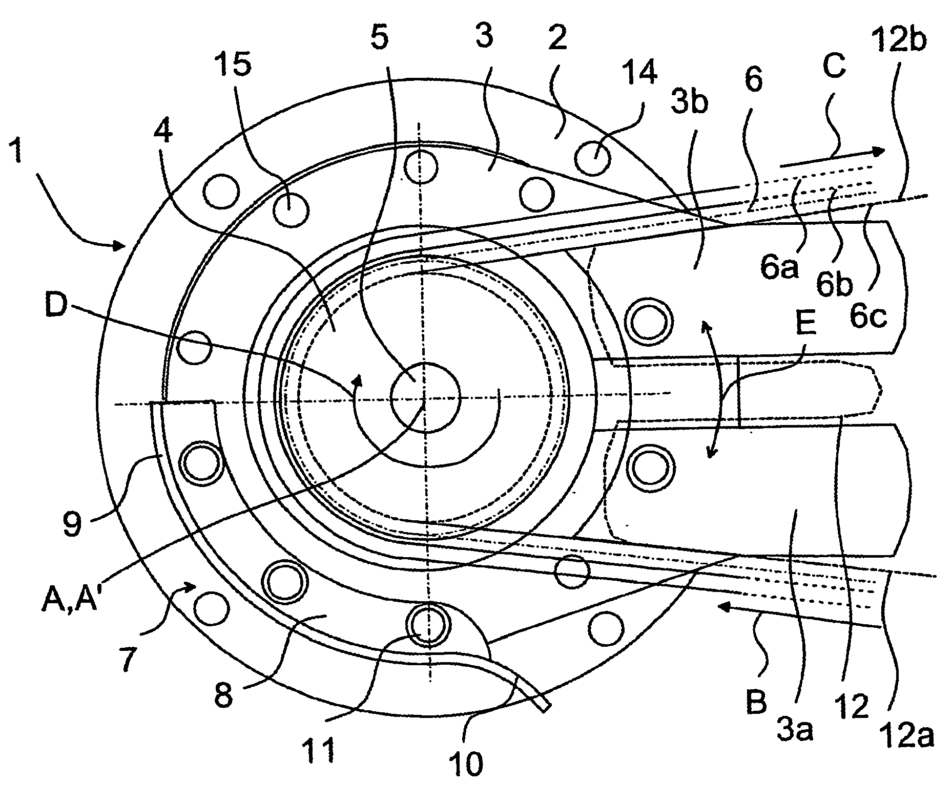
[0018] In FIG. 1 the safety system 7 is shown in such a manner that it is fastened to a holder 3 in a sawing apparatus 1, said holder rotating around a rotation axis A. A guide bar 12 is also fastened to the holder 3, which guide bar is shown only partly in FIG. 1 by means of broken lines. For this purpose the holder 3 comprises projecting areas 3a and 3b, against which the guide bar 12 is positioned and pressed with clamping means known as such, which form a part of the holder 3. The structure of the holder 3 is known as such, wherein it complies especially with the publication WO 98 / 53666. According to another embodiment, the holder 3 is similar to the holder disclosed in the publication U.S. Pat. No. 5,802,946. The type of the holder 3 and its clamping means can also be similar to the other holders of the guide bar, depending on the sawing apparatus in which the safety system is applied. The holder 3 is especially of such a type that it is utilized for turning the guide bar 12 (r...


PUM

PropertyMeasurementUnit
distanceaaaaaaaaaa
heightaaaaaaaaaa
heightaaaaaaaaaa

Abstract

Method and safety device for a breaking saw chain, wherein the safety device comprises a protective wall positioned in the vicinity of the drive gear drawing the saw chain in such a manner that it is capable of receiving the movement of the tail of the broken saw chain and to guide said tail in a controlled manner with the rest of the saw chain into the desired direction, wherein at the same time the strong swinging movement of said tail is prevented, and said protective wall is fastened to movable members that are arranged to hold the protective wall in the correct location during sawing in relation to the saw chain whose incoming direction varies during the operation. In particular, the protective device is placed in a sawing apparatus comprising a frame part, a holder for a guide bar, means for driving the saw chain and for performing the sawing, as well as means for moving the protective wall in phase with the guide bar holder, wherein said means are preferably implemented by using the guide bar holder.

Description

FIELD OF THE INVENTION [0001] The invention relates to a method in a sawing apparatus of a forest machine for preventing the whipping movement of a saw chain breaking during sawing. The invention relates to a sawing apparatus of a forest machine. BACKGROUND OF THE INVENTION [0002] In forest machines, a harvester head is typically used, which is arranged to perform the felling of a growing tree and the manipulation of the tree after the felling at the forest work place. When the harvester head is fastened to the end of a boom assembly in a forest machine, its task is to grip an upright standing tree and cut it, allow the movement of the tree substantially onto the horizontal plane in a controlled manner and to delimb and cut the tree. The tree trunk is fed through the delimbing means of the harvester head substantially on horizontal plane in such a manner that the travel of the tree is stopped at intervals, wherein the tree trunk is cut at a suitable point by means of sawing. The fee...

Claims


Application Information

Patent Timeline
Patent Type & Authority Applications(United States)
IPC IPC(8): B27B17/00A01G23/091B27G19/00
CPCA01G23/091B27B17/00B27G19/003Y10T83/04
Inventor ANNALA, MARKKU
Owner JOHN DEERE FORESTRY OY
Why Eureka
Try Eureka