Vehicle driving apparatus

Inactive Publication Date: 2006-05-25
TOYOTA JIDOSHA KK
View PDF9 Cites 36 Cited by
  • Summary
  • Abstract
  • Description
  • Claims
  • Application Information

AI Technical Summary

Benefits of technology

[0008] In view of the aforementioned situation, it is an object the invention to provide a vehicle driving apparatus which can be assembled with a h

Problems solved by technology

This may lead to a problem that foreign matter such as iron powder and so forth adheres to a magnetized portion of the rotor, for example.
Such a configuration leads to a positional error between a rotor axis and a stator axis due to a positional error of the crankshaft

Method used


Image

  • Vehicle driving apparatus
  • Vehicle driving apparatus
  • Vehicle driving apparatus

Examples


Embodiment Construction

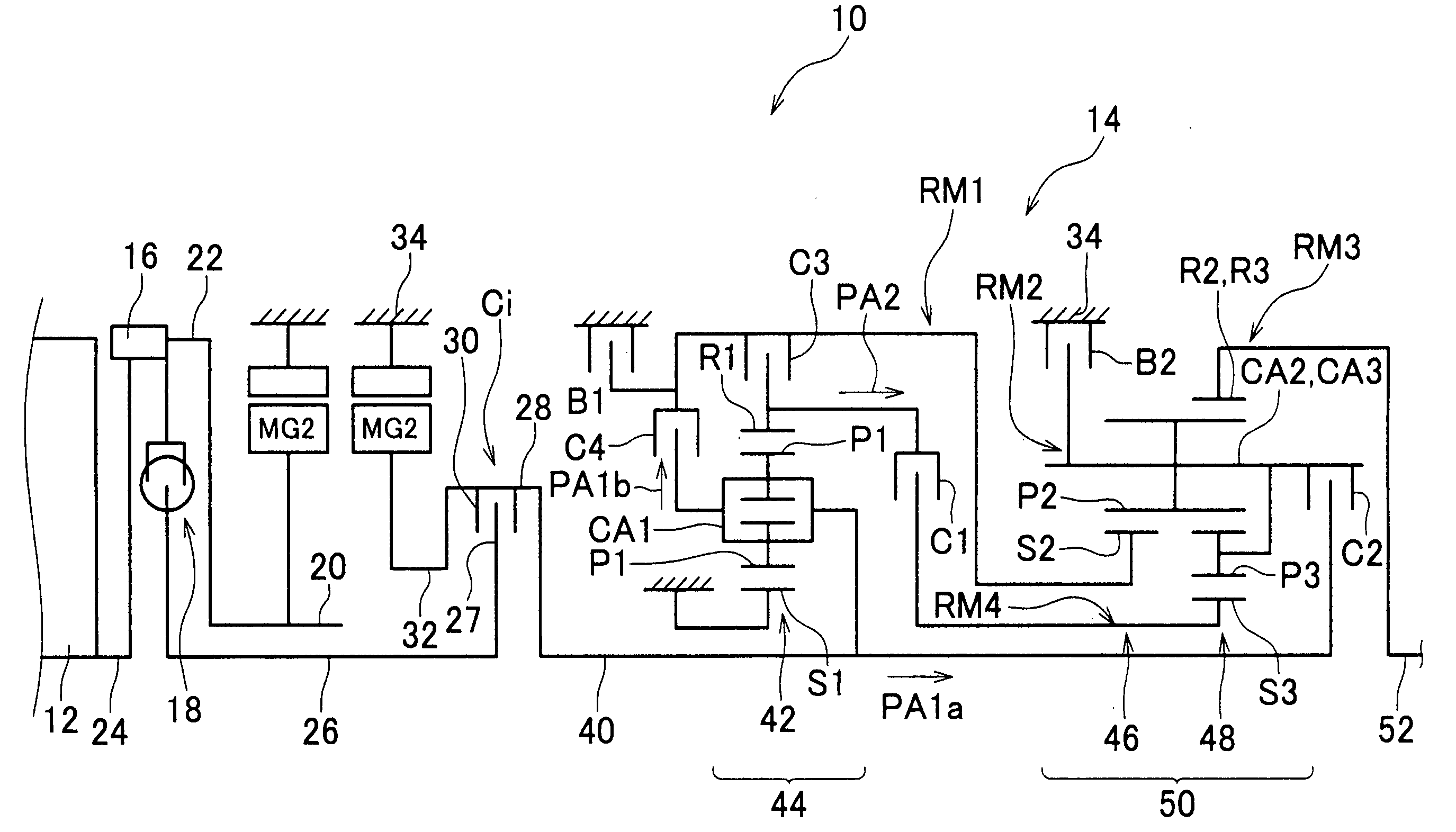
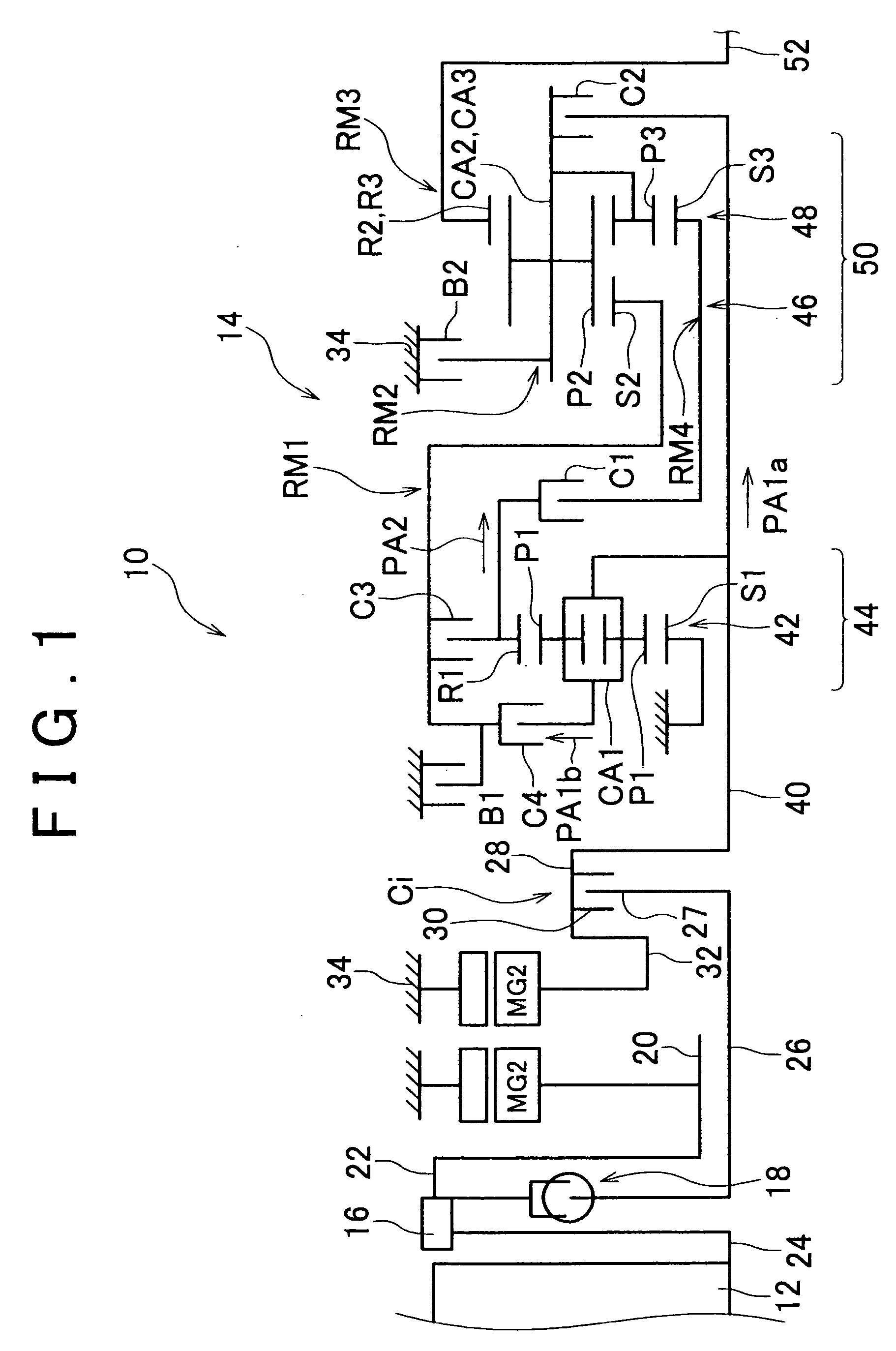
[0022] Next, exemplary embodiments of the invention will be described with reference to the drawings. FIG. 1 is a schematic diagram showing the configuration of a vehicle driving apparatus (which will be referred to as “driving apparatus” hereafter) 10 according to one exemplary embodiment of the invention. The driving apparatus 10 can be suitably employed in FR vehicles by being mounted in the longitudinal direction thereof. Specifically, the driving apparatus 10 includes an engine 12, a first electric motor-generator MG1, a second electric motor-generator MG2, and an automatic multi-speed transmission (which will be simply referred to as “automatic transmission” hereafter) 14, in that order in the axial direction. A flywheel 16 and a damper 18, which serve as vibration damping devices, are provided between the first electric motor-generator MG1 and the engine 12. A rotor shaft 20 of the first motor-generator MG1 is connected to a crankshaft 24 of the engine 12 through the flywheel...


PUM


Abstract

A rotor shaft of a first electric motor is connected to a crankshaft of the engine by being fit to a transmitting member that is coupled to the crankshaft. The stator and rotor shaft of the first electric motor are supported by a case housing the first electric motor.

Description

INCORPORATION BY REFERENCE [0001] The disclosure of Japanese Patent Applications No. 2004-337168 and No. 2004-338167 both filed on Nov. 22, 2004 including the specification, drawings and abstracts is incorporated herein by reference in their entireties. BACKGROUND OF THE INVENTION [0002] 1. Field of the Invention [0003] The invention relates to a vehicle driving apparatus used for vehicles such as automobiles and so forth. [0004] 2. Description of the Related Art [0005] As a driving source for a vehicle, vehicle driving apparatuses including an engine and an electric motor are known. For example, such a vehicle driving apparatus is disclosed in U.S. patent application Publication No. 2003 / 0127262 A1. The vehicle driving apparatus disclosed in this publication includes an engine and first and second electric motors. A flange of a rotor of the first electric motor is directly connected to a crankshaft of the engine with bolts. Furthermore, a damper is disposed on the opposite side of ...

Claims


Application Information

Patent Timeline
IPC IPC(8): B60K6/00B60K6/26B60K6/365B60K6/40B60K6/405B60K6/442B60K6/48
CPCB60K6/26B60K6/365B60K6/40B60K6/405B60K6/442B60K6/48F16H3/663F16H3/666F16H2200/006F16H2200/0086F16H2200/2007F16H2200/2023Y02T10/6221Y02T10/6234Y02T10/62
Inventor TABATA, ATSUSHITAGA, YUTAKAMIYAZAKI, TERUFUMIIBARAKI, RYUJI
Owner TOYOTA JIDOSHA KK
Why Eureka
Try Eureka