Eureka AIR delivers breakthrough ideas for toughest innovation challenges, trusted by R&D personnel around the world.

Load leveling and electrolysis system

a load leveling and electrolysis technology, applied in the field of load leveling and electrolysis systems, can solve the problems of not taking into account the cost benefits of generated oxygen, and achieve the effects of minimizing all causes of resistive (1r) loss, effective and cost-efficient load leveling, and keeping resistance very low

Active Publication Date: 2006-05-25
EOS ENERGY TECH HLDG LLC
View PDF3 Cites 10 Cited by
  • Summary
  • Abstract
  • Description
  • Claims
  • Application Information

AI Technical Summary

Benefits of technology

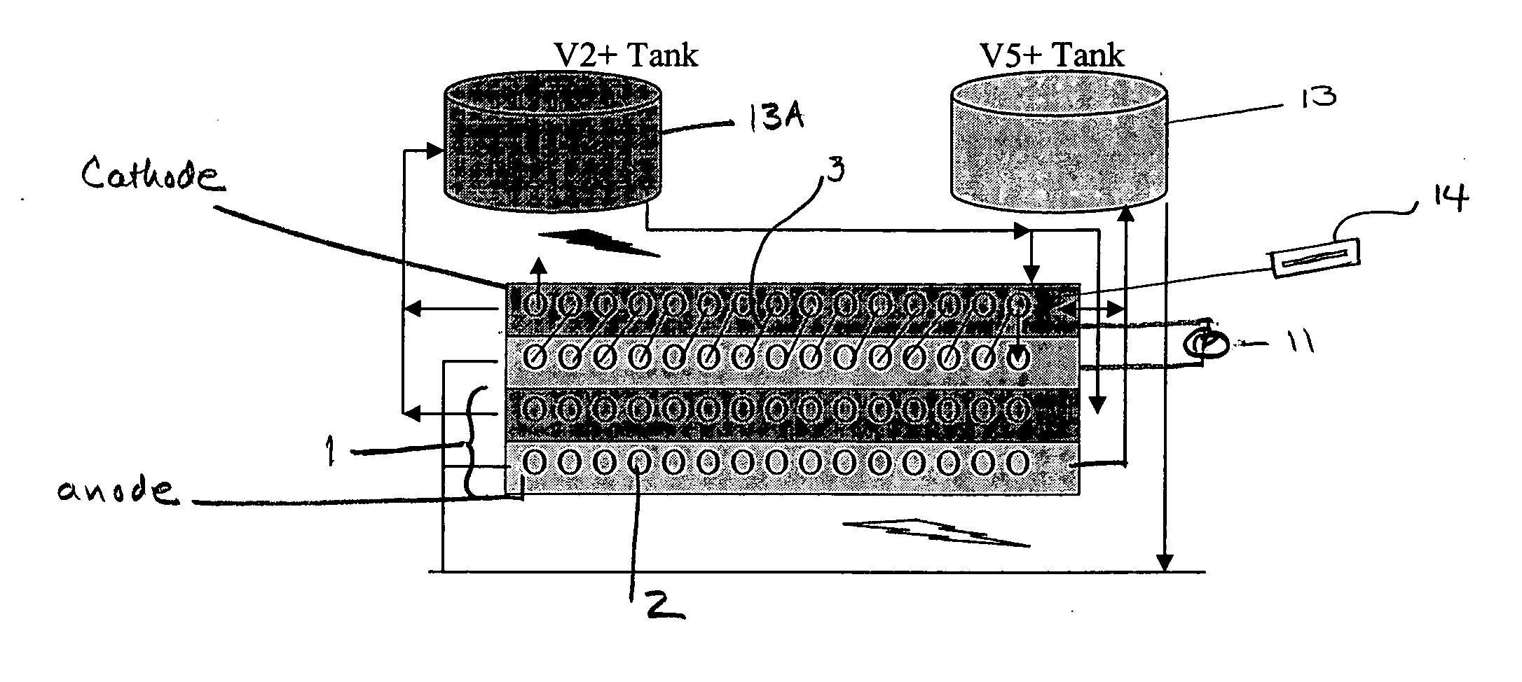
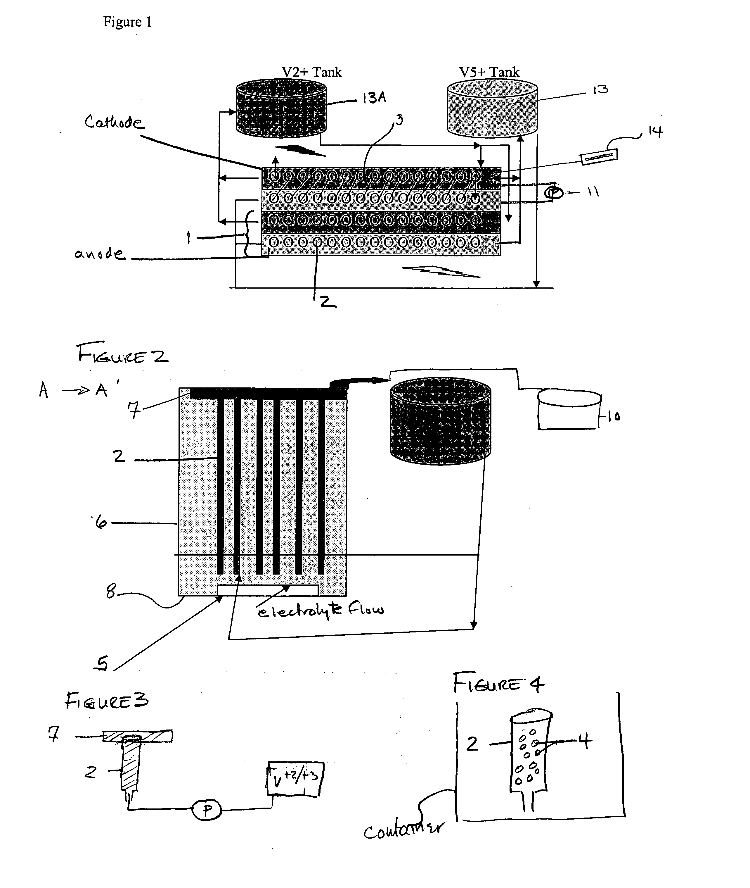
[0009] The present invention which addresses the resistive, overpotential and polarization losses discussed above, provides an economically robust system for load leveling as well as electrolysis units for the production of hydrogen. On a large-scale basis, the novel system is capable of being integrated with an electric utility to achieve effective and cost-efficient load leveling at even spike loads without causing damage to the infrastructure of a utility, thereby helping to stabilize and even prevent a generating plant that has just disconnected from a grid from shutting down. The system of the present invention is modular and can be connected in various series-parallel connections to achieve the desired configuration. The present invention, for the sake of simplicity is referred to the L-Cell for load leveling, or VE electrolyzer for hydrogen production, and in which the use of expensive membranes or MEAs, respectively, are not required. The L-Cell minimizes all causes of resistive (1R) losses by a combination of electrochemistry and mechanical design which keeps resistance very low.
[0034] The L-Cell operates at over 80% efficiency. Its novel cell design addresses all three major problems of a cell, namely, overpotential, polarization and IR losses. An important element of the L-Cell design is the use of electrodes made from suitable porous materials such as woven plastic closths or carbon felts, formed, for example in the shape of a tube. Alternatively, a suitable conductive material may be incorporated into a tube made from a porous metal, again, for example, a carbon felt. The L-Cell design is both inexpensive and robust and can be built for about $300,000 to $500,000 / megawatt. It is also versatile enough to contribute to the reduction of sulfur emissions at a power plant at a great savings compared to lime scrubbers and can reduce the costs of NOx scrubbing.

Problems solved by technology

This does not take into account the cost benefits of generated oxygen, as well as pollution abatement savings that can be achieved by the system.

Method used


Image

  • Load leveling and electrolysis system
  • Load leveling and electrolysis system

Examples


Embodiment Construction

[0039] The present invention provides a truly scalable load leveler and electrolyzer at less than $500,000 / megawatt. Each chamber of the L-Cell is preferrably designed as a large structure in order to allow for large current loads, as well as accompanying required high water and gas flows to match the high power inputs.

[0040] The materials used in the construction of the L-Cell containers, tanks are relatively inexpensive, such as PVC or PE or PP or many other plastics suitable for use with the chosen electrolyte, e.g., H2SO4. The electrodes can be made of many suitable porous materials having a conductive material either inside of an electrode or formed as at least a part of the electrode. Said material must not deteriorate in the electrolyte, yet it must efficiently conduct electricity. Carbon and metal materials are generally preferred. Each L-Cell uses about 1.5 volts per cell (depending on the chosen ion couples) to charge; and each group of cells may contain as many cells as ...


PUM

PropertyMeasurementUnit
net voltageaaaaaaaaaa
electric energyaaaaaaaaaa

Abstract

The invention is a device for electrical load-leveling and / or electrolysis. A housing contains pairs of electrodes made from or containing a porous material. The electrodes are filled respectively with an anolyte and a catholyte, which is an ionic couple such as Vanadium +2 / +3. A non-permi-selective barrier membrane with openings may be included to substantially separate the electrode pair. The device results in reduced resistive, over-potentials and polarization losses, and may be scaled-up for integration into an electric utility.

Description

[0001] The present invention relates to a system for electrical load leveling for the production of electricity and hydrogen; and a Vanadium-based electrolysis system for the efficient and cost-effective production of hydrogen. BACKGROUND OF THE INVENTION [0002] Many electrical power sources have problems in matching production to demand. On a small scale, a solar power or wind turbine system that generates power on an intermittent basis, but nevertheless requires power on a broader demand basis. This problem is the same for the entire North American grid system where power producers are constantly trying to balance the power demand with many different integrated sources of power generation. A practical solution to this problem is needed. Several attempts at using various types of batteries (lead-acid, re-dox, etc.) have all been economic if not technical failures. The only current method of energy storage for load leveling is that known as pump-storage, in which energy is stored in...

Claims


Application Information

Patent Timeline
Patent Type & Authority Applications(United States)
IPC IPC(8): C25B9/00C25C7/02C25B11/04C25B11/00C25B9/19C25B9/17
CPCB01D53/326C25B1/04C25B9/00H01M4/624H01M4/8615H01M8/0656H01M8/188Y02E60/366Y02E60/50Y10S204/04Y02E60/36Y02E60/10
Inventor AMENDOLA, STEVEN
Owner EOS ENERGY TECH HLDG LLC
Why Eureka
Eureka Blog
Learn More