Electrolytic cell for electrolyzed water generator

Inactive Publication Date: 2006-05-25
HONDA MOTOR CO LTD
View PDF3 Cites 3 Cited by
  • Summary
  • Abstract
  • Description
  • Claims
  • Application Information

AI Technical Summary

Benefits of technology

[0010] An object of the present invention is to provide an electrolytic cell for electrolyzed water generator which can overcome such problems as described above and surely supply sufficient electric power to the electrodes of a membrane-electrode assembly.

Problems solved by technology

However, in this structure, the electrodes arranged in a manner sandwiching the diaphragm are separated from each other with a large space therebetween, and hence the electric resistance between the electrodes is large, resulting in a problem that the electrolysis efficiency in relation to the applied electric power is low.
However, in the electrolytic cell disclosed in the above publication, the circulation resistance is large, and hence when the amount of electrolyzed water produced in a unit time is increased, the equipment concerned inevitably becomes large insize.
However, in the above described membrane-electrode assembly, it is not easy to connect lead wires to the electrodes, and it is not easy to supply electric power through the lead wires.
Accordingly, even when the current collectors are brought into contact with the electrode surfaces, it is not easy to supply electric power from the current collectors to the electrodes, and hence further improvement is desired.

Method used


Image

  • Electrolytic cell for electrolyzed water generator
  • Electrolytic cell for electrolyzed water generator
  • Electrolytic cell for electrolyzed water generator

Examples


example

[0028] The embodiment of the present invention will be described below in detail with reference to the accompanying drawings.

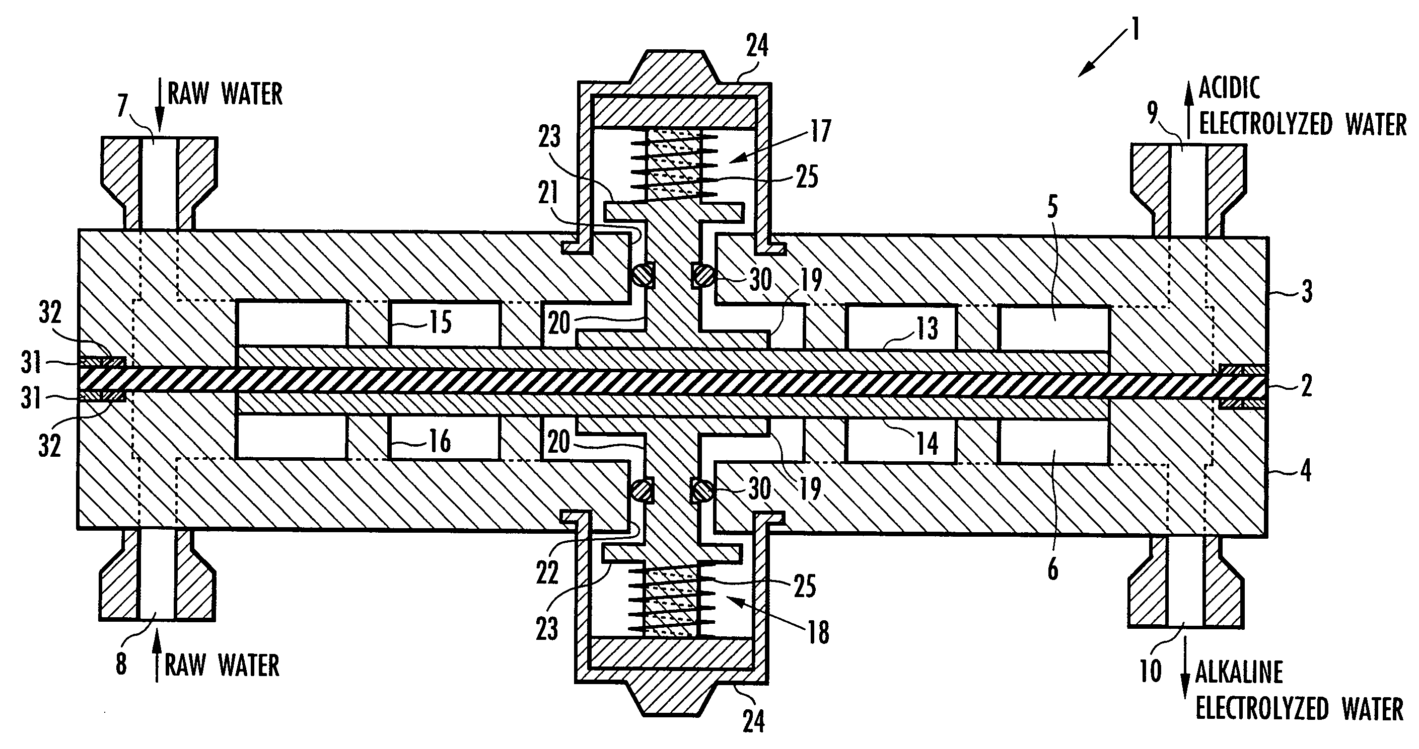
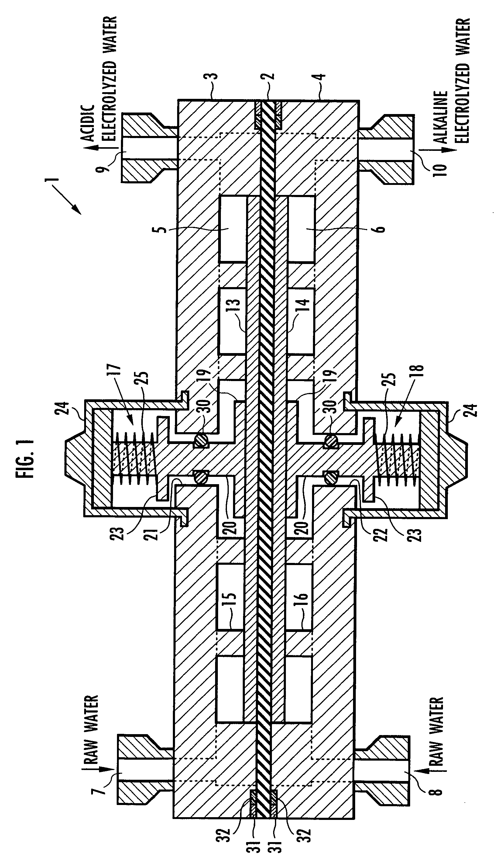
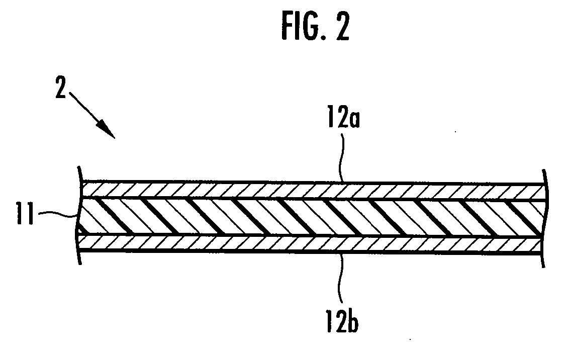
[0029] An electrolytic cell 1 of the present invention is to be used in electrolyzed water generator, and comprises as shown in FIG. 1 a membrane-electrode assembly 2, and electrolysis chamber cases 3 and 4 sandwiching the membrane-electrode assembly 2, wherein the electrolysis chamber cases 3 and 4 comprise thereinside electrolysis chambers 5 and 6, respectively. Consequently, in the electrolytic cell 1, a pair of electrolysis chambers 5 and 6 is arranged opposite to each other through the membrane-electrode assembly 2.

[0030] The electrolysis chamber cases 3 and 4 comprise respectively raw water feed ports 7 and 8 for feeding raw water respectively to the electrolysis chambers 5 and 6, and electrolyzed water take-out ports 9 and 10 for taking electrolyzed water respectively out of the electrolysis chambers 5 and 6. The raw water feed ports 7 and 8 a reconne...


PUM

PropertyMeasurementUnit
Pressureaaaaaaaaaa
Flow rateaaaaaaaaaa
Electrical conductoraaaaaaaaaa

Abstract

An electrolytic cell 1 comprises electrolysis chambers 5 and 6 arranged opposite to each other through a diaphragm 11, raw water feed means 8 and 7, electrodes 12a and 12b arranged in the electrolysis chambers 5 and 6 in a manner sandwiching the diaphragm 11, and electrolyzed water take-out means 9 and 10 for taking out electrolyzed water obtained by electrolyzing raw water. The electrolytic cell 1 comprises a membrane-electrode assembly 2 formed so as to cause the electrodes 12a and 12b to respectively adhere to both surfaces of the diaphragm 11, mesh current collectors 13 and 14 respectively arranged opposite to the electrodes 12a and 12b, and a plurality of protrusions 15 and 16. The electrolytic cell 1 comprises connecting members 17 and 18 connecting the mesh current collectors 13 and 14 to an external electric power supply in a manner penetrating the outer walls of the electrolysis chambers 5 and 6, and resilient members 25 for energetically pressing the connecting members 17 and 18 toward the mesh current collectors 13 and 14. The electrolytic cell 1 comprises a plurality of the protrusions 15 and 16, and the connecting members 17 and 18, respectively at positions opposite to each other on both sides of the membrane-electrode assembly 2. The current collectors 13 and 14 are formed of a corrosion resistant conductive material. The electrodes 12a and 12b are formed of a porous material containing a conductive powder.

Description

BACKGROUND OF THE INVENTION [0001] 1. Field of the Invention [0002] The present invention relates to an electrolyzed water generator which produces acidic and alkaline electrolyzed water, by electrolyzing raw water fed into a pair of electrolysis chambers arranged opposite to each other through an ion permeable diaphragm, and by applying a voltage to a pair of electrodes respectively arranged in the electrolysis chambers in a manner sandwiching the diaphragm. More specifically, the present invention relates to an electrolytic cell in the electrolyzed water generator. [0003] 2. Description of the Related Art [0004] There is known an electrolyzed water generator which produces electrolyzed water by use of an electrolytic cell comprising a pair of electrolysis chambers arranged opposite to each other through an ion permeable diaphragm and a pair of electrodes respectively arranged in the electrolysis chambers in a manner sandwiching the diaphragm. In the electrolyzed water generator, e...

Claims


Application Information

Patent Timeline
IPC IPC(8): C25B9/00C25B9/23
CPCC02F1/4618C02F2201/46115Y02E60/366Y02E60/36C25B1/04
Inventor MIYASHITA, KOHICHIMUTO, GO
Owner HONDA MOTOR CO LTD
Why Eureka
Try Eureka