Layer system comprising a silicon layer and a passivation layer, method for production a passivation layer on a silicon layer and the use of said system and method

a silicon layer and passivation layer technology, applied in the field of layer systems, can solve the problems of easy spread in an uncontrolled manner, significant risk of creeping extremely quickly behind applied passivation layers, etc., and achieve the effect of strengthening the “primary” passivation

Active Publication Date: 2006-05-25
ROBERT BOSCH GMBH
View PDF32 Cites 23 Cited by
  • Summary
  • Abstract
  • Description
  • Claims
  • Application Information

AI Technical Summary

Benefits of technology

[0020] However, it is advantageous in many cases to reinforce the “primary” passivation by separating a substantially thicker, teflon-like layer from a plasma discharge according to the method described in German Patent No. 42 41 045 using, for example, C4F8, or C3F6, or even C4F6, or C5F8 as the passivation gas providing teflon-forming monomers. The two passivation gases mentioned last crosslink particularly well and advantageously form particularly dense teflon layers which are diagonally crosslinked within themselves. This creates a teflon-like film over the second partial layer without damaging the first inorganic partial layer due to the effect of ions and (CF2) radicals. It is possible in

Problems solved by technology

However, the use of ClF3, and with limitation also BrF3, has the disadvantage that it easily spreads in an uncontrolled manner over micro-channel structures or even nano-channel structures, so that there is a significant risk of it creeping extremely quickly behind applied passivation layers, teflon-like side wall passivation layers according to German Patent No.

Method used


Image

  • Layer system comprising a silicon layer and a passivation layer, method for production a passivation layer on a silicon layer and the use of said system and method
  • Layer system comprising a silicon layer and a passivation layer, method for production a passivation layer on a silicon layer and the use of said system and method

Examples


Embodiment Construction

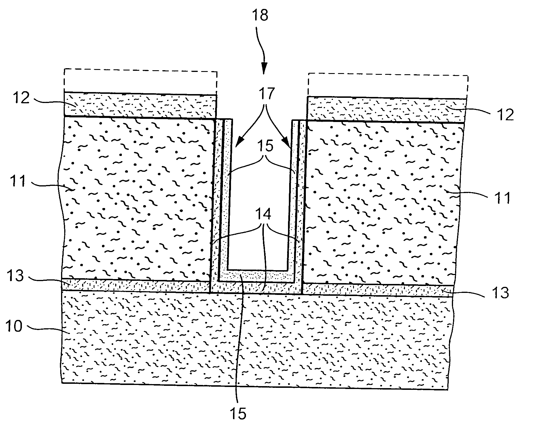
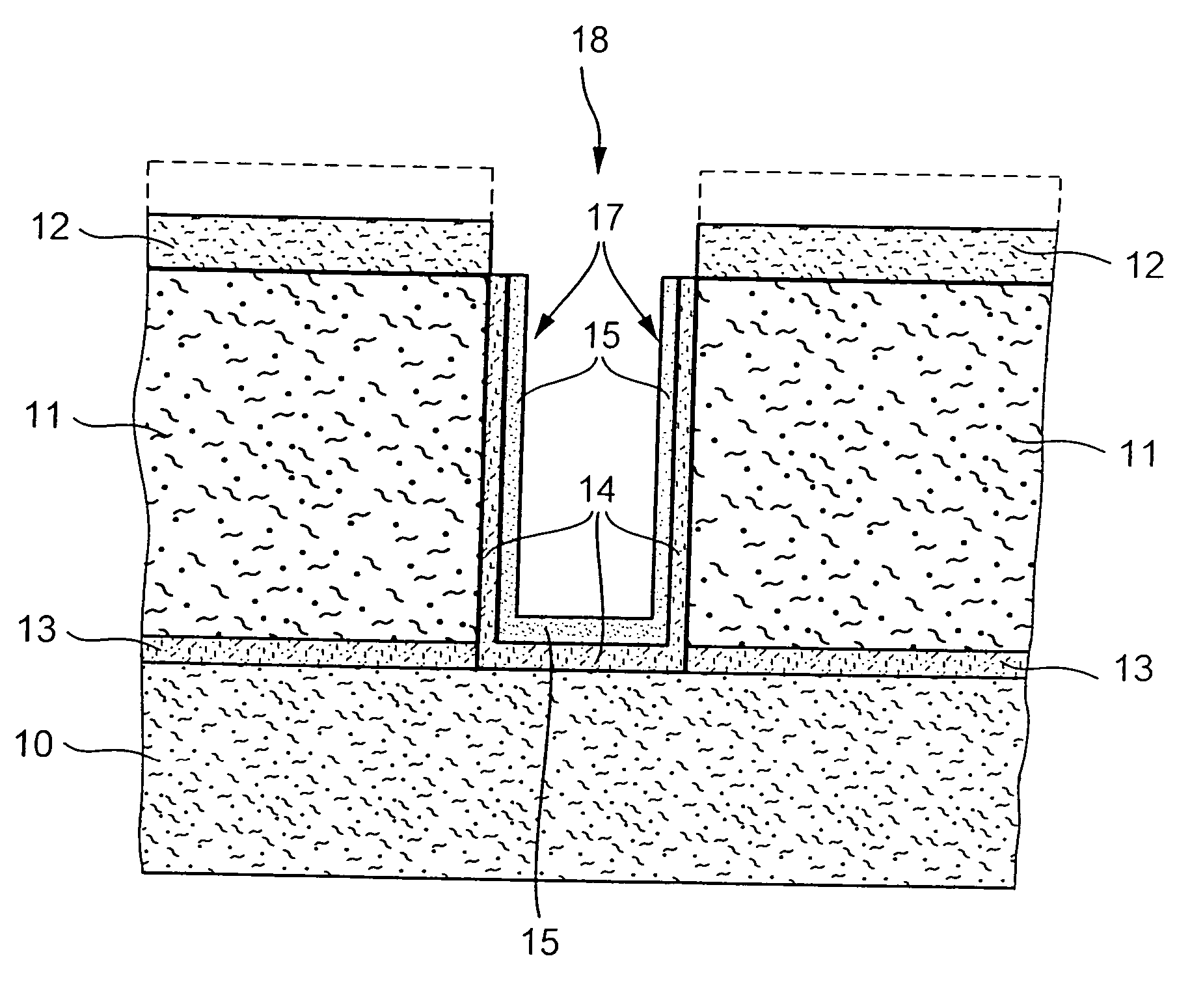
[0024] An exemplary embodiment of a layer system having a silicon layer and a passivation layer applied on the surface in certain areas and a method for creating such a passivation layer on a silicon layer are explained in the Figure. In particular, one starts initially from a silicon wafer having a layer system, suitable for processing according to German Published Patent Application No. 197 47 455, and including buried oxide layers, polysilicon layers, and a functional silicon layer, a photo resist masking defining the structures to be created in the silicon layer being applied thereto.

[0025] A first silicon layer 10, made of polysilicon for example, is provided on a substrate (not shown in the Figure) and possibly existing buried oxide layers, a separating layer 13, made of silicon oxide for example, being situated on first silicon layer 10. A second silicon layer 11 as a functional silicon layer, a photo resist mask 12 being situated thereon, is applied to separating layer 13. ...


PUM

PropertyMeasurementUnit
Thicknessaaaaaaaaaa
Thicknessaaaaaaaaaa
Thicknessaaaaaaaaaa

Abstract

A layer system is described including a silicon layer and a passivation layer which is applied at least regionally to the silicon layer's surface, the passivation layer having a first, at least largely inorganic partial layer and a second partial layer, the second partial layer being made of an organic compound including silicon or containing such a material. In particular, the second partial layer is structured in the form of a “self-assembled monolayer.” Furthermore, a method is described for creating a passivation layer on a silicon layer, a first, inorganic partial layer being created on the silicon layer and a second partial layer, containing an organic compound including silicon or being made thereof, being created at least in certain areas on the first partial layer. Both partial layers form the passivation layer. The described layer system or the described method is particularly suited for creating self-supporting structures in silicon.

Description

FIELD OF THE INVENTION [0001] The present invention relates to a layer system having a silicon layer and a passivation layer, a method for creating a passivation layer on a silicon layer and use of this layer system or this method. BACKGROUND INFORMATION [0002] In a method known, for example, from German Patent No. 44 20 962, for manufacturing self-supporting MEMS structures (MEMS=“micro electromechanical structures”) by combining anisotropic and isotropic etching processes, trenches or deep structures having perpendicular side walls are initially anisotropically etched into a silicon substrate using a reactive plasma. After achieving the intended etch depth and subsequent to a longer lasting passivation step for removing a teflon-like film, a longer lasting etching step is carried out in which the etch bottom of the trench is initially cleared of a formed teflon polymer via sputtering, followed by an isotropic underetching of the self-supporting MEMS structures to be created. Due t...

Claims


Application Information

Patent Timeline
IPC IPC(8): H01L29/08B81C1/00H01L21/312H01L21/316
CPCB81C1/00571H01L21/02123H01L21/02238H01L21/02252H01L21/02337H01L21/02343H01L21/02359H01L21/3121H01L21/31612B81C2201/016B81B2203/033Y10S438/958H01L21/302H01L21/31B82Y40/00
Inventor LAERMER, FRANZMUELLER, LUTZBERNHARD, WINFRIED
Owner ROBERT BOSCH GMBH
Why Eureka
Try Eureka