Interdigitated back contact solar battery structure with passivation contact structure and preparation method of solar battery structure

A contact structure and solar cell technology, applied in the field of solar cells, can solve problems such as coexistence of positive and negative electrodes, difficulty in welding battery components, and impact on battery reliability, and achieve low cost, reduced space complexity, and reduced welding difficulties.

Pending Publication Date: 2018-10-12
TAIZHOU LERRISOLAR TECH CO LTD
View PDF4 Cites 14 Cited by
  • Summary
  • Abstract
  • Description
  • Claims
  • Application Information

AI Technical Summary

Problems solved by technology

[0004] The back structure of the currently used interdigitated back contact solar cells usually uses a through-type p-type doped region and an n-type doped region, and then uses a through-type or non-through-type electrode combined with an insulating material for positive and negative insulation. Therefore, when preparing an IBC battery, an additional insulator preparation process is sometimes required, and due to the coexistence of po

Method used


Image

  • Interdigitated back contact solar battery structure with passivation contact structure and preparation method of solar battery structure
  • Interdigitated back contact solar battery structure with passivation contact structure and preparation method of solar battery structure
  • Interdigitated back contact solar battery structure with passivation contact structure and preparation method of solar battery structure

Examples


preparation example Construction

[0056] A method for preparing an interdigitated back-contact solar cell with a passivation contact structure, comprising the steps of:

[0057] 1) Texturing the surface of the front side of the n-type silicon substrate 1;

[0058] 2) Form a backside passivation tunneling layer 11 on the backside of the n-type silicon substrate 1; then pattern the second doped region 4 and the first doped region 3 on the backside of the n-type silicon substrate 1, so that the first doped region 3 Alternating with the second doped region 4 in the form of interdigitated fingers; preparing an n-type surface doped layer or a p-type positive surface doped layer on the front side of the silicon substrate 1;

[0059] 3) Prepare a rear passivation film 5 on the back of the n-type silicon substrate 1, and prepare a front passivation and anti-reflection film 2 on the front of the n-type silicon substrate 1;

[0060] 4) Prepare battery electrodes on the back passivation film 5 .

[0061] Step 2 also inc...

Embodiment 1

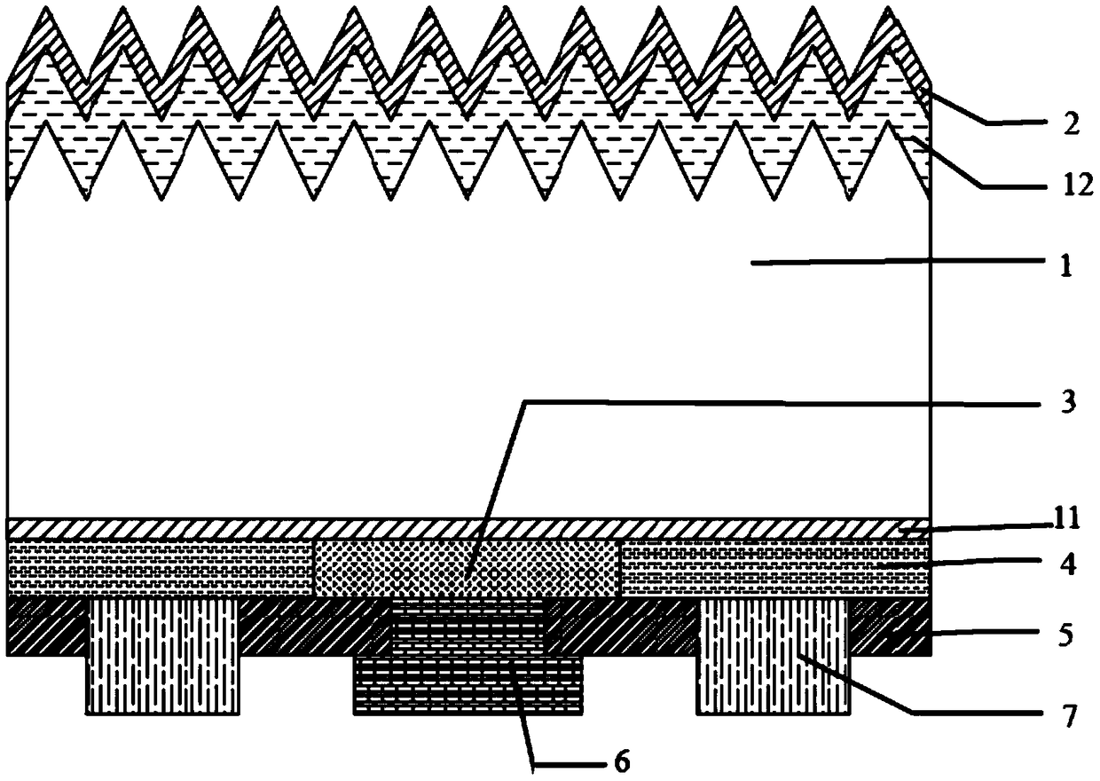
[0066] like figure 1 and Figure 7 As shown, a structure of interdigitated back-contact solar cells, this embodiment uses n-type silicon wafers as the substrate, this cell includes from top to bottom: front passivation and anti-reflection film, n-type front surface doping Layer 12, n-type silicon substrate 1, back passivation tunneling layer 11, back doped film layers 3 and 4, back passivation film and battery electrodes; wherein the back doped film layer has the first doped region 3 on the back and the back doped film layer The first doped region 3 on the back side of the second doped region 4 is composed of one or more of polysilicon, amorphous silicon, and microcrystalline silicon, and is doped with group V elements; the second doped region 4 on the back is made of polysilicon, amorphous silicon Composed of one or more of crystalline silicon and microcrystalline silicon, and doped with Group III elements;

[0067] The first doped region 3 on the back side and the second d...

Embodiment 2

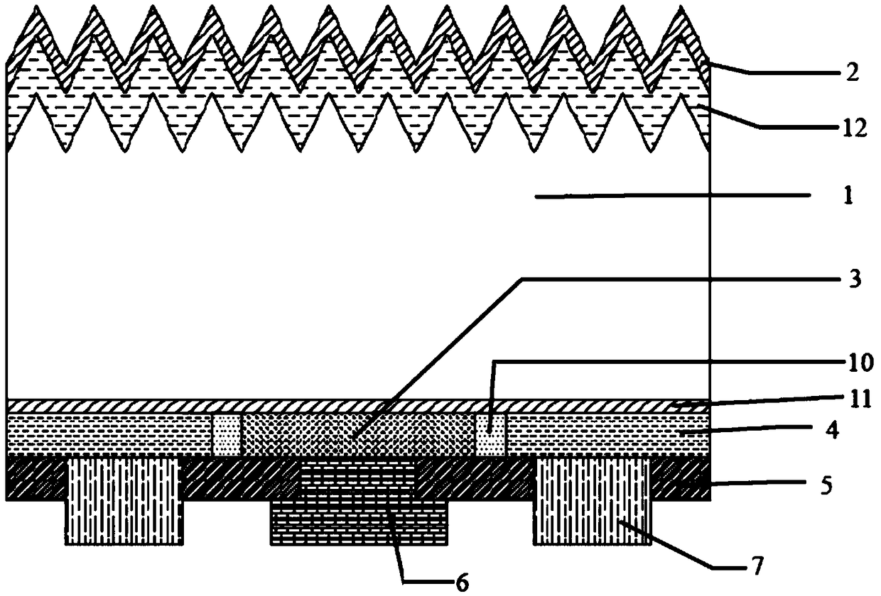
[0080] like figure 2 and Figure 7 , Figure 8 As shown, but the front surface doped layer 12 uses p-type as the front surface doped layer 12. In this case, a floating pn junction is formed on the front surface, which can also enhance the passivation of the front surface. Other structures are similar to those of Embodiment 1.

[0081] The structure of this interdigitated back-contact solar cell, this cell includes from top to bottom: front passivation and anti-reflection film, p-type front surface doped layer 12, n-type silicon substrate 1, back passivation tunneling Layer 11, the back first doped region 3 and the back second doped region 4, the back passivation film and the battery electrode; the back first doped region 3 is made of one or more of polysilicon, amorphous silicon, and microcrystalline silicon The second doped region 4 on the back is composed of one or more of polycrystalline silicon, amorphous silicon, and microcrystalline silicon, and is doped with group I...


PUM

PropertyMeasurementUnit
Widthaaaaaaaaaa
Thicknessaaaaaaaaaa
Thicknessaaaaaaaaaa

Abstract

The invention relates to an interdigitated back contact solar battery structure with a passivation contact structure and a preparation method of the solar battery structure. The solar battery structure sequentially comprises a front-side passivation and anti-reflection film,a front-side doping layer,an n-type silicon substrate,a back-side passivation tunneling layer,a back-side doping layer,a back-side passivation film and battery electrodes from top to bottom in the thickness direction of a silicon substrate; the back-side doping layer is composed of a first doping region and a second dopingregion,and the first doping region and the second doping region are identical in structure and are interdigitated; the battery electrodes comprise the positive electrode and the negative electrode,thepositive electrode is in contact with the second doping region,and the negative electrode is in contact with the first doping region. By means of the structure,the possibility of current leakage in aspace can be well avoided. The reliability performance of a battery in a later product is improved,and the process difficulty of a battery assembly is reduced.

Description

technical field [0001] The invention belongs to the technical field of solar cells, and in particular relates to a cell structure of an interdigitated back contact solar cell with a passivation contact structure and a preparation method thereof. Background technique [0002] At present, with the gradual depletion of fossil energy, solar cells are used more and more widely as a new energy alternative. A solar cell is a device that converts the sun's light energy into electrical energy. Solar cells use the principle of photovoltaics to generate carriers, and then use electrodes to extract the carriers, which is beneficial to the effective use of electrical energy. [0003] Interdigitated back contact battery, also known as IBC battery. Among them, IBC refers to Interdigitated backcontact. The biggest feature of the IBC battery is that the emitter and the metal contact are on the back of the battery, and the front is not affected by the shielding of the metal electrode, so i...

Claims


Application Information

Patent Timeline
IPC IPC(8): H01L31/0224H01L31/049H01L31/042H01L31/18
CPCH01L31/022441H01L31/042H01L31/049H01L31/1876Y02E10/50Y02P70/50
Inventor 李华李中兰鲁伟明靳玉鹏
Owner TAIZHOU LERRISOLAR TECH CO LTD
Why Eureka
Try Eureka