Turbomachine including an integrated electricity generator

a technology of integrated generators and turbines, which is applied in the direction of electric generator control, machines/engines, mechanical apparatus, etc., can solve the problems of increasing the number of equipment (oil pipes and pumps) inside the engine, complicating the access to the generator for maintenance purposes, etc., to reduce the weight of the engine, eliminate mechanical connections and angle takeoffs, and reduce the effect of engine weigh

Active Publication Date: 2006-05-25
SN DETUDE & DE CONSTR DE MOTEURS DAVIATION S N E C M A
View PDF7 Cites 40 Cited by
  • Summary
  • Abstract
  • Description
  • Claims
  • Application Information

AI Technical Summary

Benefits of technology

[0021] The dispositions of the invention make it possible to envisage an aeroengine in which the accessories are driven by electric motors powered by the electricity generators integrated in the engine, thus making it possible to eliminate the mechanical connections and the angle takeoffs, to reduce the weight of the engine, and to th...

Problems solved by technology

The power takeoff system and the accessory box have had difficulty in following this progress correspondingly, and they thus represent a large fraction of the volume and the weight of an engine, in particular of a low-thrust engine which is therefore small in size, particularly when...

Method used


Image

  • Turbomachine including an integrated electricity generator
  • Turbomachine including an integrated electricity generator
  • Turbomachine including an integrated electricity generator

Examples


Embodiment Construction

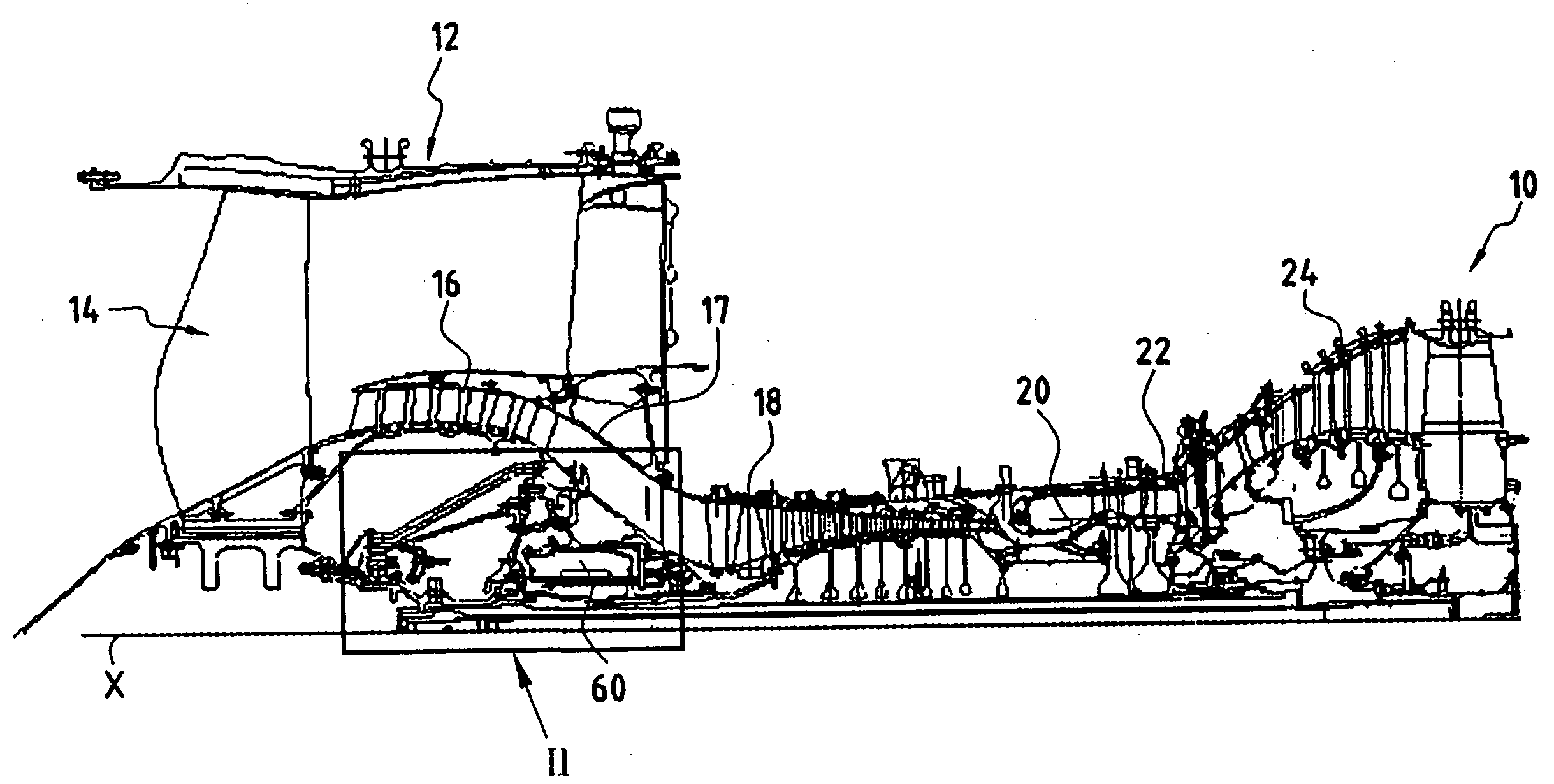
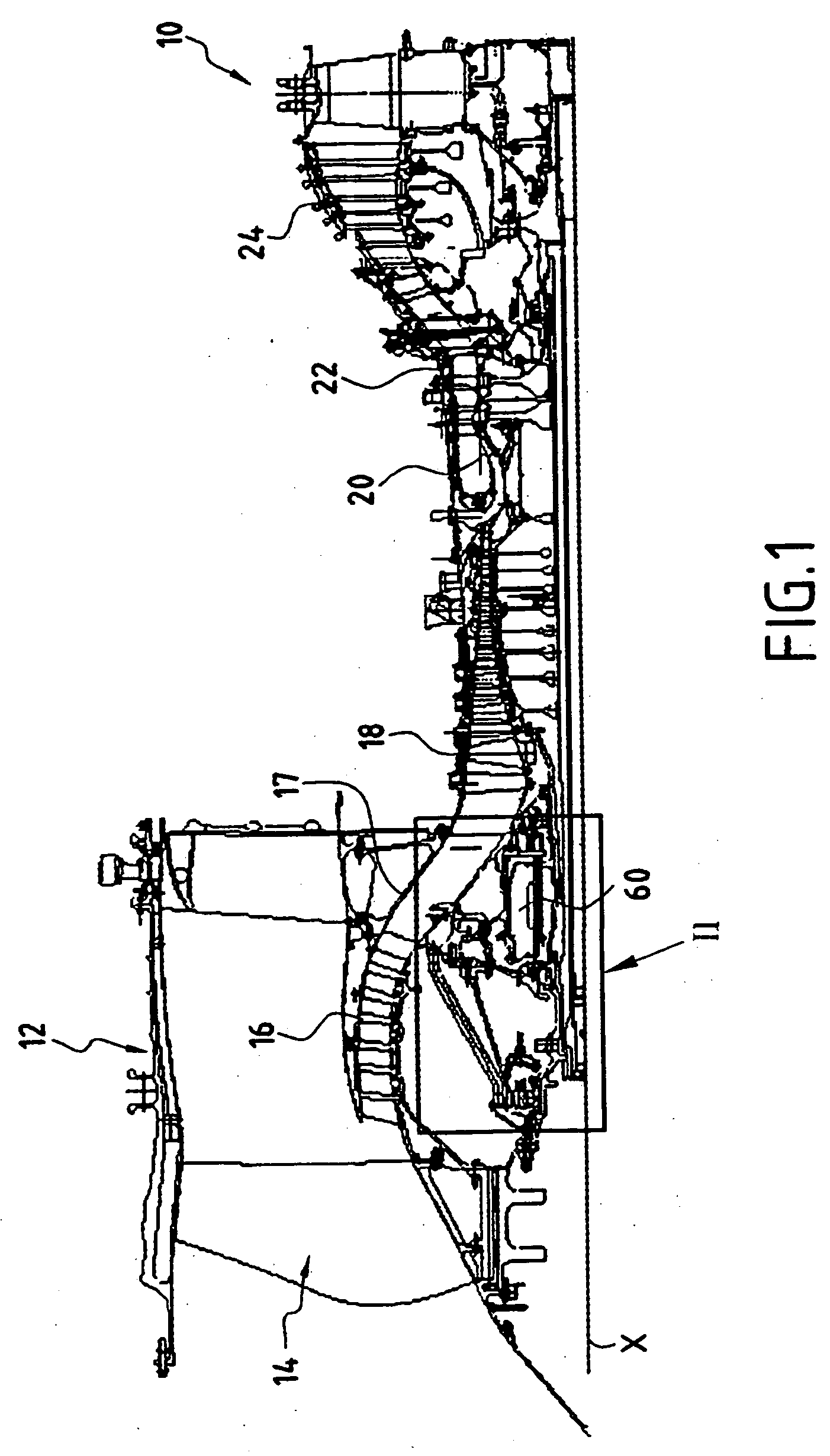
[0026]FIG. 1 shows a two-spool bypass turbojet 10 on which an electricity generator is arranged at the front in accordance with the present invention.

[0027] More precisely, the turbojet 10 of axis X conventionally comprises a peripheral cowl 12 (shown in part) containing, from left to right in FIG. 1 (i.e. from upstream to downstream in the front to rear direction of air flow), and in succession: the fan 14; a low-pressure compressor 16; a high-pressure compressor 18; a combustion chamber 20; a high-pressure turbine 22; and a low-pressure turbine 24.

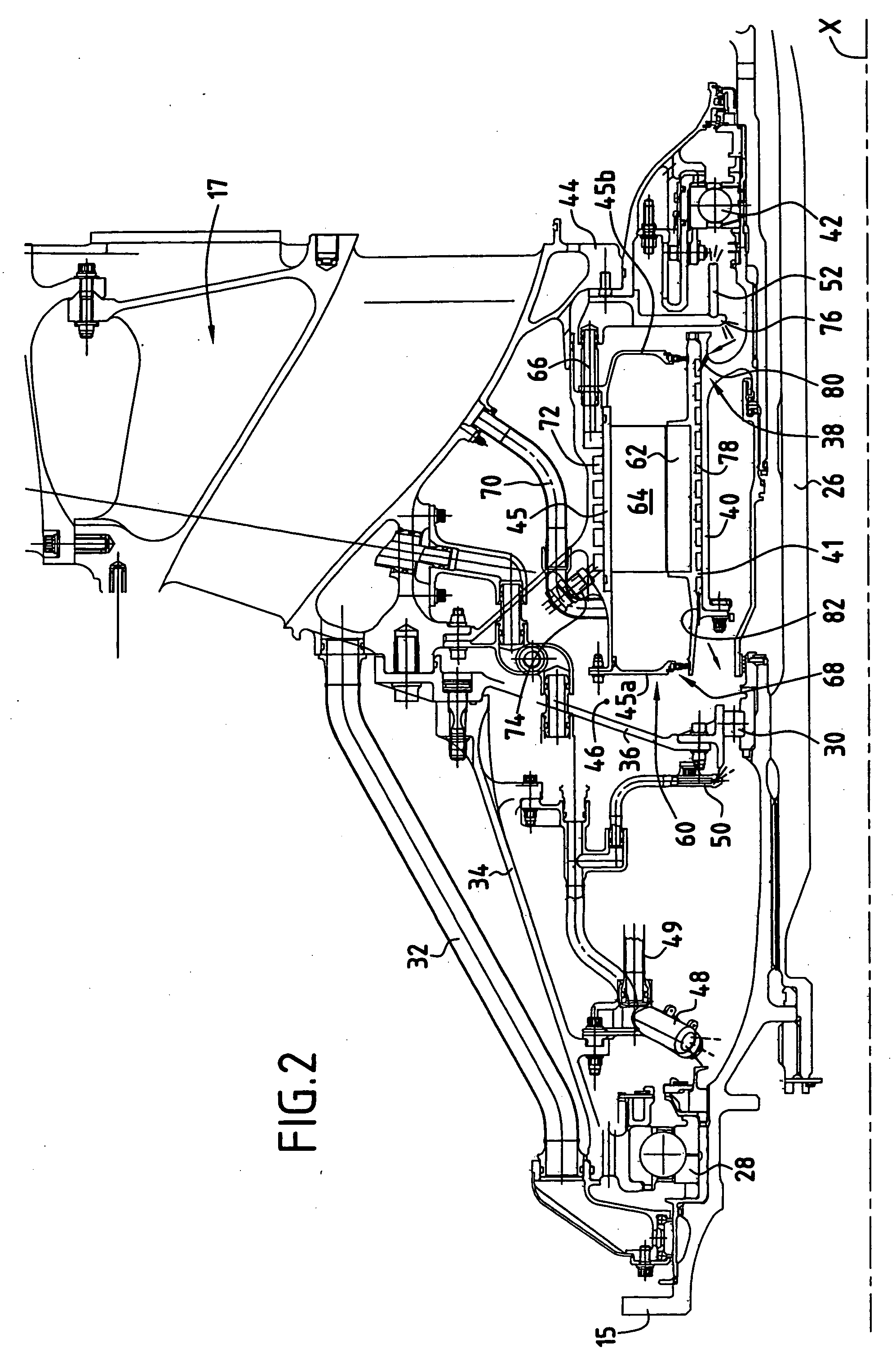
[0028] Finally, in accordance with the present invention, the turbojet 10 is fitted with an electricity generator 60 situated at the front of the turbojet 10 (to the left in FIG. 1) in a zone that is cold.

[0029] More precisely, with reference to FIG. 2, it can be seen that the electricity generator 60 is disposed between the low-pressure compressor 16 and the high-pressure compressor 18, level with the intermediate casing 17 between t...


PUM


Abstract

The invention relates to a turbomachine comprising a high-pressure spool, an axial compressor of axis X mounted on a rotor and comprising a casing and at least one rear bearing disposed between the casing and the rotor of said compressor, said turbomachine further comprising an electricity generator coaxial with said spool and including a primary magnetic circuit that is constrained to rotate with said rotor of the compressor and a secondary magnetic circuit that is secured to said casing. In characteristic manner, said electricity generator is disposed upstream from said rear bearing and includes at least a first cooling circuit surrounding said secondary magnetic circuit and extended by a nozzle for lubricating said rear bearing.

Description

[0001] The invention relates to a turbomachine, and more particularly to a turbojet that includes an integrated electricity generator coaxial with the shaft of the turbomachine. BACKGROUND OF THE INVENTION [0002] In a conventional engine, the accessory box fitted with fuel pumps, bearing lubricant pumps, hydraulic pumps for controlling various members, electricity generators, and the starter, is located outside the engine and receives power taken from the engine by means of a radial shaft and angle takeoffs. [0003] Over the years, the increases in the compression ratios and in the inlet temperatures to the turbine, and also the improvements in materials and efficiency, have led to a constant reduction in the size of engines so as to obtain an ever increasing ratio of weight / thrust, and this applies both to civilian applications and to military applications. [0004] The power takeoff system and the accessory box have had difficulty in following this progress correspondingly, and they ...

Claims


Application Information

Patent Timeline
IPC IPC(8): F02C6/00
CPCF01D15/10F01D25/18F02C7/268F02K3/06Y02T50/671F05D2260/85F05D2220/76Y02T50/60
Inventor BOUILLER, PHILIPPEMORREALE, SERGEROUSSELIN, STEPHANE
Owner SN DETUDE & DE CONSTR DE MOTEURS DAVIATION S N E C M A
Why Eureka
Try Eureka