Circuit and method for sensing open-circuit lamp of a backlight unit and display device with circuit for sensing open-circuit lamp of backlight unit
- Summary
- Abstract
- Description
- Claims
- Application Information
AI Technical Summary
Benefits of technology
Problems solved by technology
Method used
Image

Examples
first embodiment
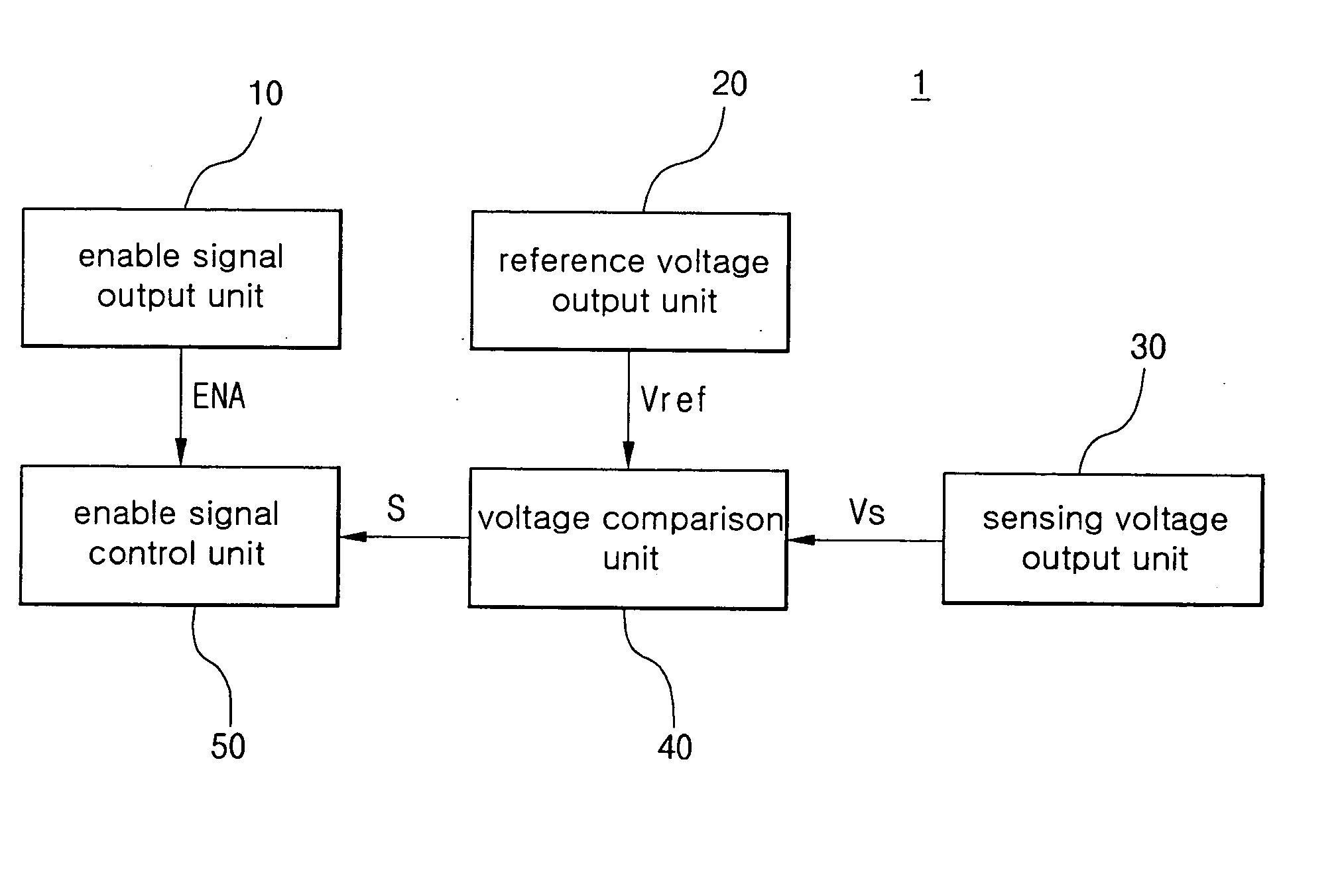
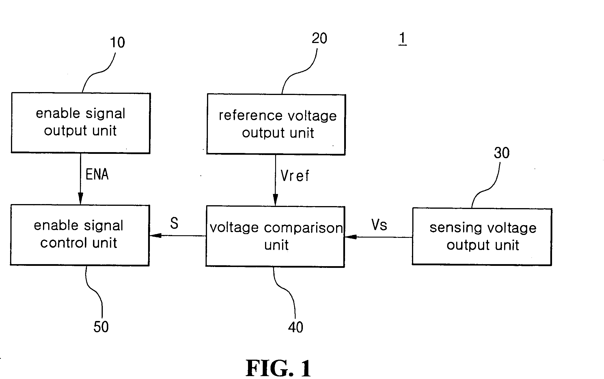
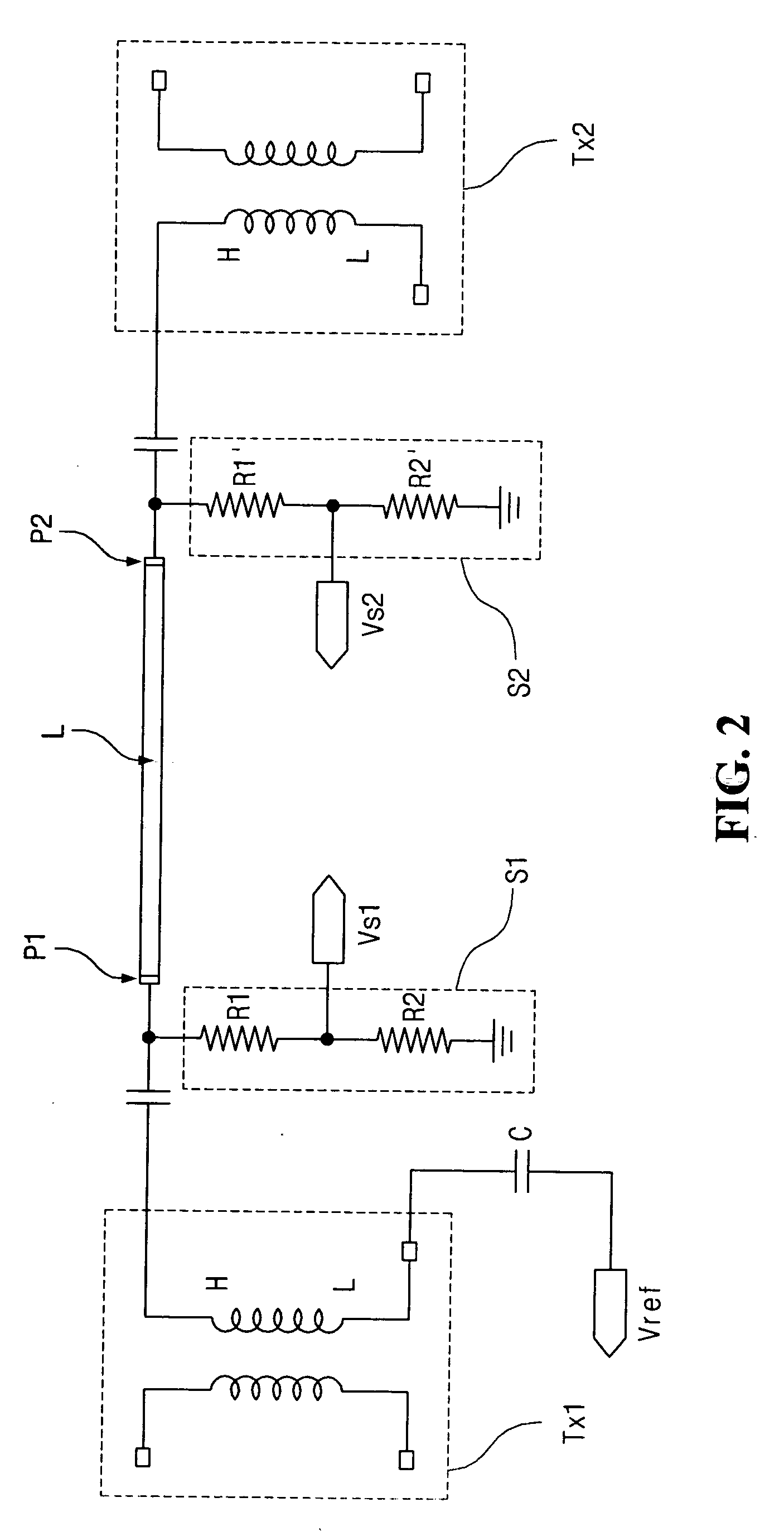
[0037]FIG. 2 is a circuit diagram illustrating a part of a circuit for sensing an open-circuit lamp of a backlight unit according to the present invention. In FIG. 2, voltage-dividing circuits S1 and S2 are connected to both electrodes P1 and P2 of a lamp L as the sensing voltage output unit 30 of FIG. 1. Each of the voltage-dividing circuits S1 and S2 includes division resistors R1 and R2 or R1′ and R2′ connected in series and outputs a sensed voltage Vs1 or Vs2.
[0038] A fluorescent lamp is driven by boosting an inputted power from about 220V AC (alternating current) voltage to about 1000 to 1500 V AC voltage through the transformers Tx2 and Tx2 which apply the boosted power to the electrodes P1 and P2 of the lamp L. In an embodiment, the division resistors R1 and R2 or R1′ and R2′ may be formed such that the sensed voltages divided by the voltage-dividing circuits S1 and S2 are about several volts (V). In addition, a low voltage L at a secondary coil of one transformer Tx1 may be ...
third embodiment
[0049]FIG. 6 is a bottom view illustrating another sensing voltage output unit of a circuit for sensing an open-circuit lamp according to the present invention. As illustrated in FIG. 6, a plurality of sensing holes 112 are formed only in the respective regions corresponding to the lamps L1, L2, . . . , Lm−1, and Lm and the conductive patterns C1, C2, . . . , Cm−1, and Cm or C1′, C2′, . . . , Cm−1′, and Cm′.
[0050] In the third embodiment, the cover bottom 110 and the conductive patterns C1, C2, . . . , Cm−1, and Cm or C1′, C2′, . . . , Cm−1′, and Cm′ are used as the sensing voltage output unit 30 of FIG. 1. When one electrode of a lamp is open-circuit, a voltage at the electrode is increased due to the infinite impedance, and an induced voltage is induced from an electric field around the lamp. The induced voltage is changed along with the change of the electric field. Thus, the induced voltage is used as the sensed voltage Vs. A plurality of sensed voltage Vs are compared with the ...
fourth embodiment
[0055] In the fourth embodiment, a sensed voltage Vs is outputted from the sensing cable 140 due to the induced voltage at each exposed portion 142 and is compared with the reference voltage Vref through the voltage comparison unit 40 of FIG. 1. If the lamp is determined as an open-circuit lamp as a result of the comparison, the enable signal control unit 50 of FIG. 1 will block the output of the enable signal to protect the system.
[0056] In an embodiment of the present invention, lamps may be sensed individually, and appropriate measures can be carried out. Accordingly, the system is effectively protected and a lifespan of the system is increased.
PUM
 Abstract
Description
Claims
Application Information
 - Generate Ideas
- Intellectual Property
- Life Sciences
- Materials
- Tech Scout
- Unparalleled Data Quality
- Higher Quality Content
- 60% Fewer Hallucinations
Browse by: Latest US Patents, China's latest patents, Technical Efficacy Thesaurus, Application Domain, Technology Topic, Popular Technical Reports.
© 2025 PatSnap. All rights reserved.Legal|Privacy policy|Modern Slavery Act Transparency Statement|Sitemap|About US| Contact US: help@patsnap.com