System and method for forming well-defined periodic patterns using achromatic interference lithography

Inactive Publication Date: 2006-05-25
MASSACHUSETTS INST OF TECH
View PDF13 Cites 56 Cited by
  • Summary
  • Abstract
  • Description
  • Claims
  • Application Information

AI Technical Summary

Benefits of technology

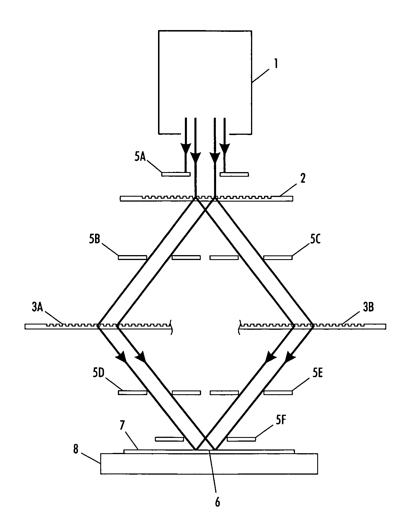
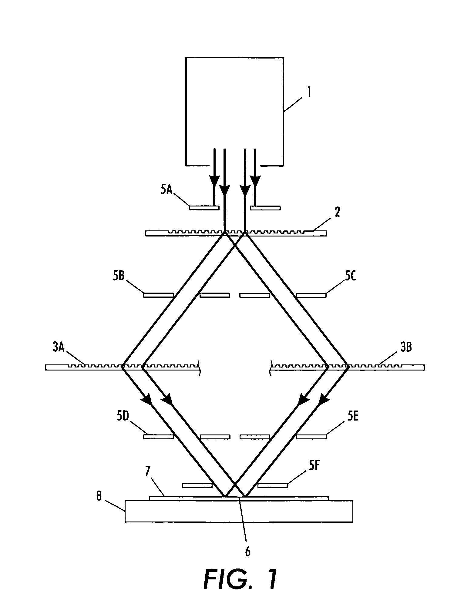
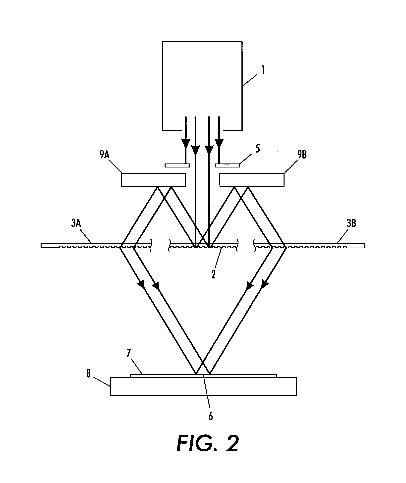
[0016] A fourth aspect of the present invention is a system for exposing a substrate to form a well-defined periodic pattern thereupon. The system includes a source of incoherent light; an optical shaping device to shape the incoherent light; a first beam splitter to split the shaped light into a plurality of beams, each beam being of a different order; and a second beam splitter to split the split beams into a plurality of beams, each beam being of a different order, the second beam splitter allowing the re-split beams to propagate to the substrate to produce an interference pattern upon the substrate

Problems solved by technology

The near-field technique, illustrated in FIGS. 15 and 16, is commonly used in industry; however, this technique suffers from a few problems.
First, any defects in, or particles on, the master grating get “printed” on the resist-coated substrate.
Secondly, there are many reflections (beams bouncing between the master grating and the substrate) that degrade the image qualit

Method used


Image

  • System and method for forming well-defined periodic patterns using achromatic interference lithography
  • System and method for forming well-defined periodic patterns using achromatic interference lithography
  • System and method for forming well-defined periodic patterns using achromatic interference lithography

Examples


Embodiment Construction

[0032] The present invention will be described in connection with preferred embodiments; however, it will be understood that there is no intent to limit the present invention to the embodiments described herein. On the contrary, the intent is to cover all alternatives, modifications, and equivalents as may be included within the spirit and scope of the present invention, as defined by the appended claims.

[0033] For a general understanding of the present invention, reference is made to the drawings. In the drawings, like reference have been used throughout to designate identical or equivalent elements. It is also noted that the various drawings illustrating the present invention are not drawn to scale and that certain regions have been purposely drawn disproportionately so that the features and concepts of the present invention could be properly illustrated.

[0034] As noted above, it is desirable to provide a system wherein the size of the exposure area can be sharply delineated and...


PUM


Abstract

A beam, from a short-coherence-length source, is split and recombined by diffraction gratings not necessarily equal in spatial period. The recombining beams overlap and expose a common area on a substrate. The exposed area on the substrate is defined or shaped by at least one aperture in the beam paths. After exposure of one shaped area, relative translation between components permits exposure of another shaped area on the substrate. Additionally or alternatively, by introducing either rotation or translation between components during each exposure, the exposed area is made larger than the original shaped area.

Description

GOVERNMENT RIGHTS NOTICE [0001] The present invention was made with US Government support under Grant (Contract) Number, DAAG55-98-1-0130, awarded by DARPA, and Grant (Contract) Number, DMR-9871539, awarded by NSF. The US Government has certain rights to this invention.FIELD OF THE PRESENT INVENTION [0002] The present invention relates to achromatic interference lithography for providing an interference pattern in a resist and, in particular, to provide an interference pattern in a resist so that the resist is exposed to form a well-defined periodic pattern therein. BACKGROUND OF THE PRESENT INVENTION [0003] Conventionally, grating images have been produced by first splitting light from a highly coherent source into a plurality of light beams and then recombining the split beams. In these conventional systems, the light source must be temporally and spatially coherent to produce large-area grating images. [0004] The simplest embodiment of this type of interference lithography is sho...

Claims


Application Information

Patent Timeline
IPC IPC(8): G03H1/10
CPCG02B5/1857G02B6/02133G03F7/70408G03H1/0465G03H1/30G03H2001/0482G03H2222/20G03H2222/24G03H2223/12
Inventor SAVAS, TIMOTHY A.SMITH, HENRY I.
Owner MASSACHUSETTS INST OF TECH
Why Eureka
Try Eureka