Transmission system, signal receiver, test apparatus and test head

a transmission system and signal receiver technology, applied in the direction of synchronising signal speed/phase control, transmission monitoring, instruments, etc., can solve the problems of random jitter in the output clock of the pll and error in the transmission of the signal, and achieve the effect of high precision

Active Publication Date: 2006-05-25
ADVANTEST CORP
View PDF6 Cites 15 Cited by
  • Summary
  • Abstract
  • Description
  • Claims
  • Application Information

AI Technical Summary

Benefits of technology

[0018] The invention allows the si...

Problems solved by technology

However, the output clock of the PLL contains random jitter caused by phase noise of the VCO.
Therefore, there has been a c...

Method used


Image

  • Transmission system, signal receiver, test apparatus and test head
  • Transmission system, signal receiver, test apparatus and test head
  • Transmission system, signal receiver, test apparatus and test head

Examples


Embodiment Construction

[0025] The invention will now be described based on preferred embodiments, which do not intend to limit the scope of the invention, but exemplify the invention. All of the features and the combinations thereof described in the embodiments are not necessarily essential to the invention.

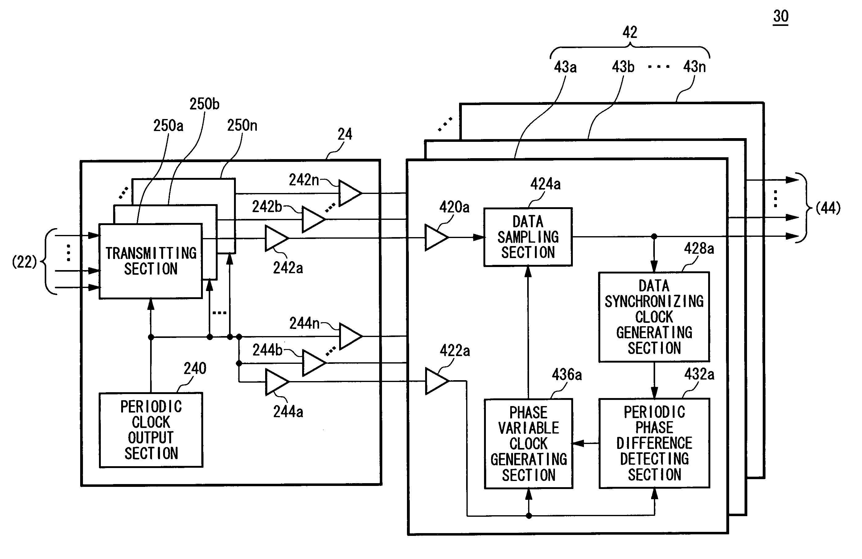
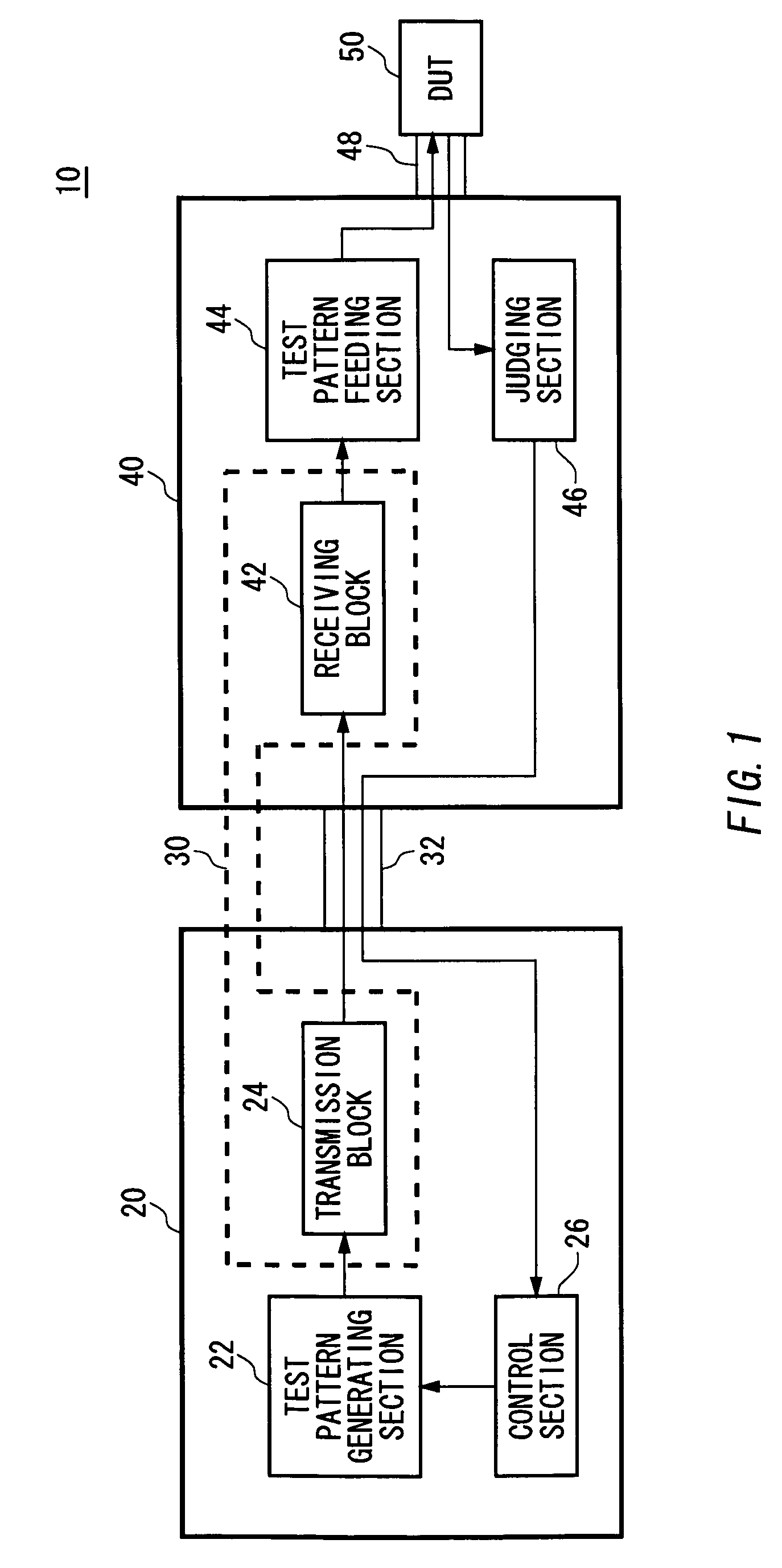
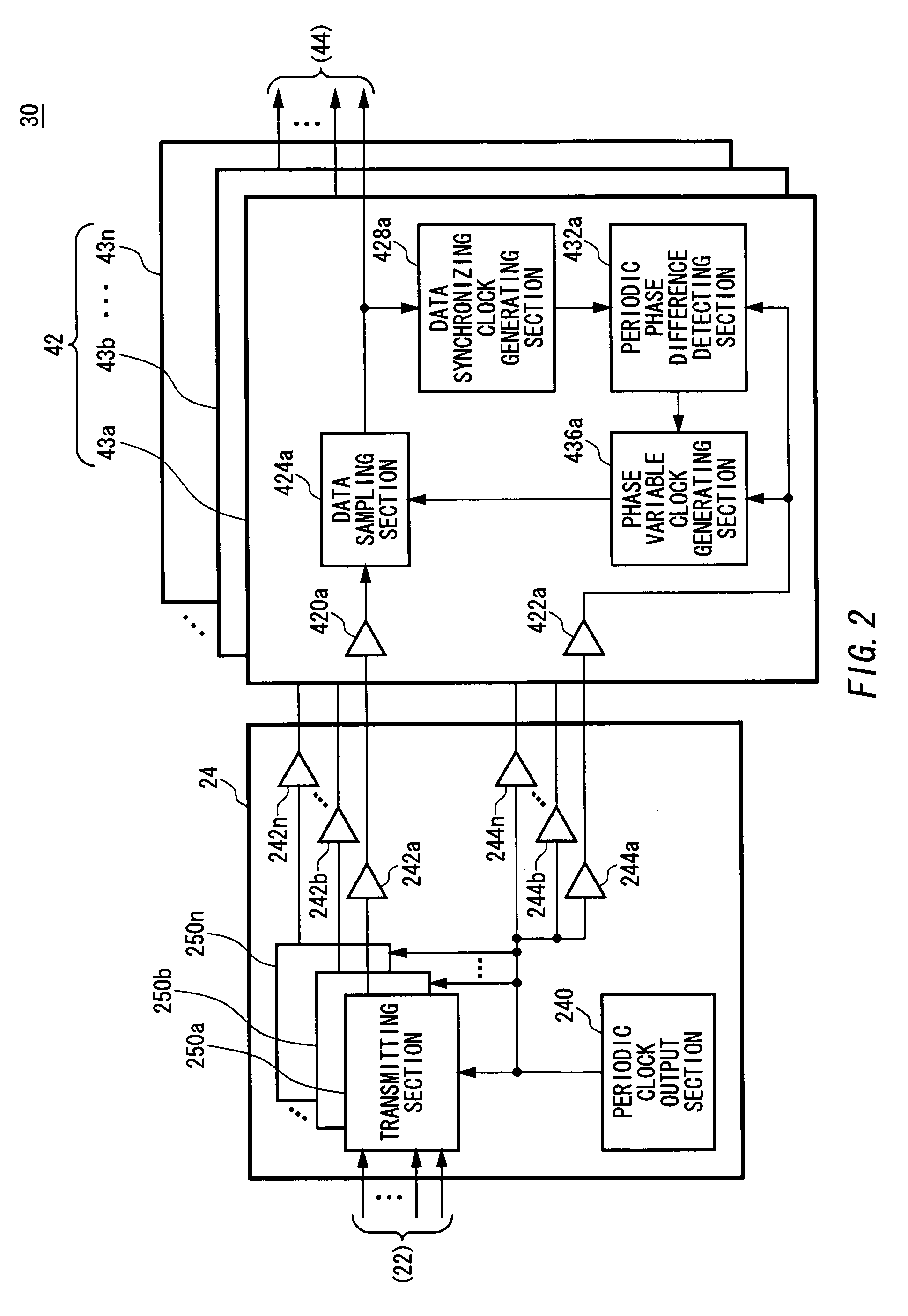
[0026]FIG. 1 is a diagram showing one exemplary configuration of a test apparatus 10 according to one embodiment of the invention. The test apparatus 10 is an apparatus for testing an electronic device (DUT) 50 and has a main frame 20, a transmission line 32, an interface 48 and a test head 40. The main frame 20 generates a test pattern for testing the electronic device 50 and transmits the test pattern to the test head 40 via the transmission line 32 such as a cable, for example. The interface 48 is a performance board for example on which the electronic device 50 is mounted and which is connected with the test head 40. The test head 40 mounts the interface 48 for example to mount the electronic devi...


PUM


Abstract

There is provided a transmission system for transmitting a transmission signal, having a periodic clock output section for outputting a periodic clock having a preset period, a transmitting section for transmitting the transmission signal in synchronism with the periodic clock and a receiving section for receiving the transmission signal transmitted from the transmitting section, wherein the receiving section has a data synchronizing clock generating section for generating, based on sampling data sampled from the transmission signal received from the transmitting section, a data synchronizing clock synchronized with variation of values of the sampling data, a periodic phase difference detecting section for detecting a phase difference between the periodic clock received from the periodic clock output section and the data synchronizing clock, a phase variable clock generating section for generating a phase variable clock obtained by varying phase of the periodic clock received from the periodic clock output section so that a variable phase difference which is a phase difference between the phase variable clock and the data synchronizing clock becomes an amount set in advance based on the phase difference and a data sampling section for sampling the sampling data from the transmission signal received from the transmitting section by receiving the transmission signal in synchronism with the phase variable clock to feed it to the data synchronizing clock generating section.

Description

CROSS REFERENCE TO RELATED APPLICATION [0001] This is a continuation application of PCT / JP 2004 / 007976 filed on Jun. 8, 2004 which claims priority from a Japanese Patent Application No. 2003-163694 filed on Jun. 9, 2003, the contents of which are incorporated herein by reference.BACKGROUND OF THE INVENTION [0002] 1. Technological Field [0003] The present invention relates to a transmission system, a signal receiver, a test apparatus and a test head. More specifically, the invention relates to a transmission system, a signal receiver, a test apparatus and a test head for transmitting a transmission signal. [0004] 2. Background Art [0005] Conventionally, there has been known a signal transmission method for transmitting a signal in synchronism with a clock outputted from a PLL (Phase Locked Loop) as disclosed, for example, in Japanese Patent Application Publication (Laid-Open) No. 2000-13218 (in particular FIG. 1) and Japanese Patent Application Publication (Laid-Open) No. 2002-198940...

Claims


Application Information

Patent Timeline
IPC IPC(8): H04B17/00H04L27/00H03L7/08G01R31/319H03L7/07H03L7/081H04L7/00H04L7/02H04L7/033
CPCG01R31/31922H03L7/07H03L7/0812H03L7/087H04L7/0012H04L7/0337H04L7/0037H03L7/0816H04L7/02H04L7/04H04L25/40
Inventor WATANABE, DAISUKEOKAYASU, TOSHIYUKI
Owner ADVANTEST CORP
Why Eureka
Try Eureka