Method and system of ct data correction

a technology of ct data and correction method, applied in the field of diagnostic imaging, to achieve the effect of effectively correcting the data associated and reducing the occurrence of detector element saturation

Active Publication Date: 2006-05-25
GENERAL ELECTRIC CO
View PDF11 Cites 70 Cited by
  • Summary
  • Abstract
  • Description
  • Claims
  • Application Information

AI Technical Summary

Benefits of technology

[0010] The present invention is a directed method and apparatus for reducing the occurrence of detector element saturation during CT data acquisition as well as effectively correcting the data associated with an over-ranging detector element that overcomes the aforementioned drawbacks.

Problems solved by technology

The data acquisition technique recognizes that for a given subject size and position that pre-subject filtering and collimating of a radiation beam may be insufficient to completely prevent detector element saturation.

Method used


Image

  • Method and system of ct data correction
  • Method and system of ct data correction
  • Method and system of ct data correction

Examples


Embodiment Construction

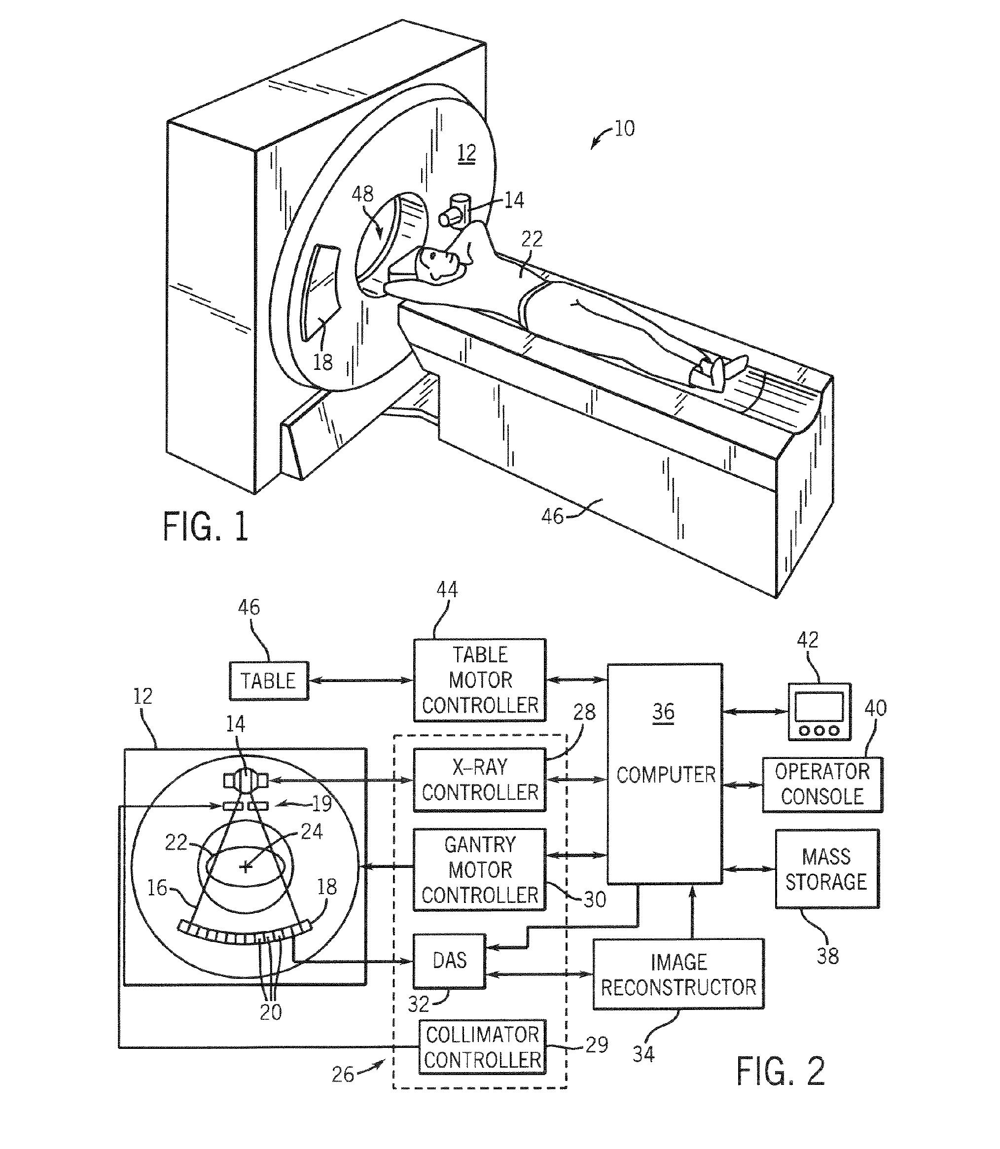
[0037] Referring to FIGS. 1 and 2, a computed tomography (CT) imaging system 10 is shown as including a gantry 12 representative of a “third generation” CT scanner. Gantry 12 has an x-ray source 14 that projects a beam of x-rays 16 toward a detector assembly 18 on the opposite side of the gantry 12. The beam of x-rays is collimated by a collimator 19. Detector assembly 18 is formed by a plurality of detectors 20 which together sense the projected x-rays that pass through a medical patient 22. Each detector 20 produces an electrical signal that represents the intensity of an impinging x-ray beam and may also be capable of providing photon or x-ray count data and energy level, and hence the attenuated beam as it passes through the patient 22. During a scan to acquire x-ray projection data, gantry 12 and the components mounted thereon rotate about a center of rotation 24.

[0038] Rotation of gantry 12 and the operation of x-ray source 14 are governed by a control mechanism 26 of CT syst...


PUM

PropertyMeasurementUnit
thicknessaaaaaaaaaa
thicknessaaaaaaaaaa
lengthaaaaaaaaaa

Abstract

An adaptive CT data acquisition system and technique is presented whereby radiation emitted for CT data acquisition is dynamically controlled to limit exposure to those detectors of a CT detector assembly that may be particularly susceptible to saturation during a given data acquisition. The data acquisition technique recognizes that for a given subject size and position that pre-subject filtering and collimating of a radiation beam may be insufficient to completely prevent detector saturation. Therefore, the present invention includes implementation of a number of CT data correction techniques for correcting otherwise unusable data of a saturated CT detector. These data correction techniques include a nearest neighbor correction, off-centered phantom correction, off-centered synthetic data correction, scout data correction, planar radiogram correction, and a number of others. The invention is applicable with energy discriminating CT systems as well as with conventional CT systems and other multi-energy CT systems, such as dual kVp-based systems.

Description

BACKGROUND OF THE INVENTION [0001] The present invention relates generally to diagnostic imaging and, more particularly, to a system and method of preventing saturation of detectors during CT data acquisition, correcting over-ranging CT detectors, and verifying the precision of a CT view correction. [0002] Typically, in radiographic systems, an x-ray source emits x-rays toward a subject or object, such as a patient or a piece of luggage. Hereinafter, the terms “subject” and “object” may be interchangeably used to describe anything capable of being imaged. The x-ray beam, after being attenuated by the subject, impinges upon an array of radiation detectors. The intensity of the radiation beam received at the detector array is typically dependent upon the attenuation of the x-rays through the scanned object. Each detector of the detector array produces a separate signal indicative of the attenuated beam received by each detector. The signals are transmitted to a data processing system ...

Claims


Application Information

Patent Timeline
Patent Type & Authority Applications(United States)
IPC IPC(8): H05G1/60A61B6/00G01N23/00G21K1/12
CPCA61B6/032A61B6/4241A61B6/482G01T1/1644G01T1/1647A61B6/027A61B6/583G06T5/002G06T5/20G06T2207/10081G06T2207/30004G06T2207/30112Y10S378/901
Inventor ARENSON, JEROME S.TKACZYK, JOHNRUIMI, DAVIDMEIRAV, ODEDDRAPKIN, EVGENYSAMSONOV, DMITRYGREENBERG, LEVDE MAN, BRUNOBASU, SAMITWU, XIAOYEDU, YANGENG
Owner GENERAL ELECTRIC CO
Why Eureka
Try Eureka