

Inducer, and inducer-equipped pump
a technology of inducer and inducer, which is applied in the direction of liquid fuel engines, marine propulsion, vessel construction, etc., can solve the problems of reducing the suction capability of the pump, affecting the reliability of the pump, and the inability to improve the blade shape of the inducer, so as to suppress the reverse flow at the inlet. , the effect of high reliability
- Summary
- Abstract
- Description
- Claims
- Application Information
AI Technical Summary
Benefits of technology
Problems solved by technology
Method used
Image

Examples
Embodiment Construction
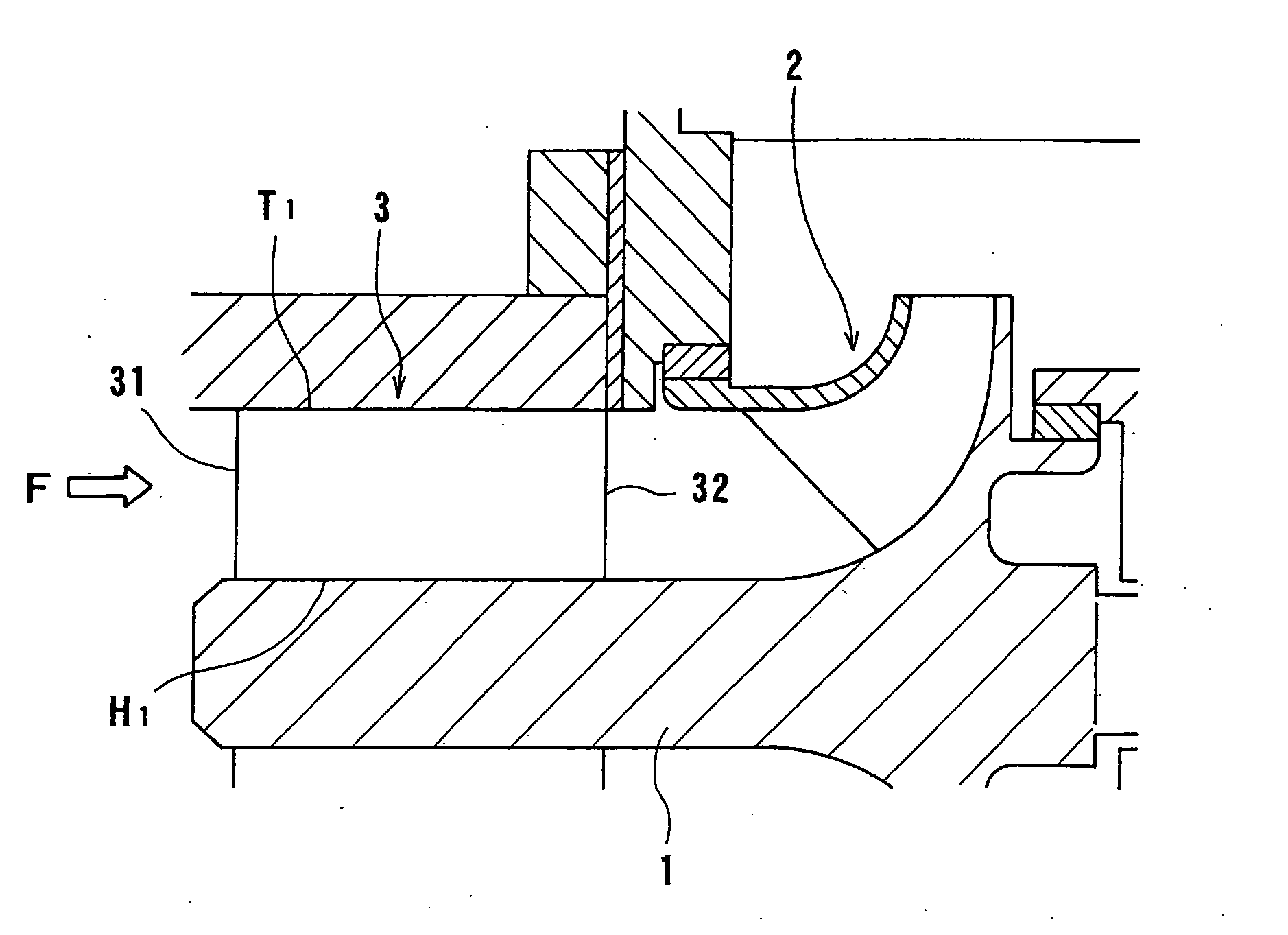
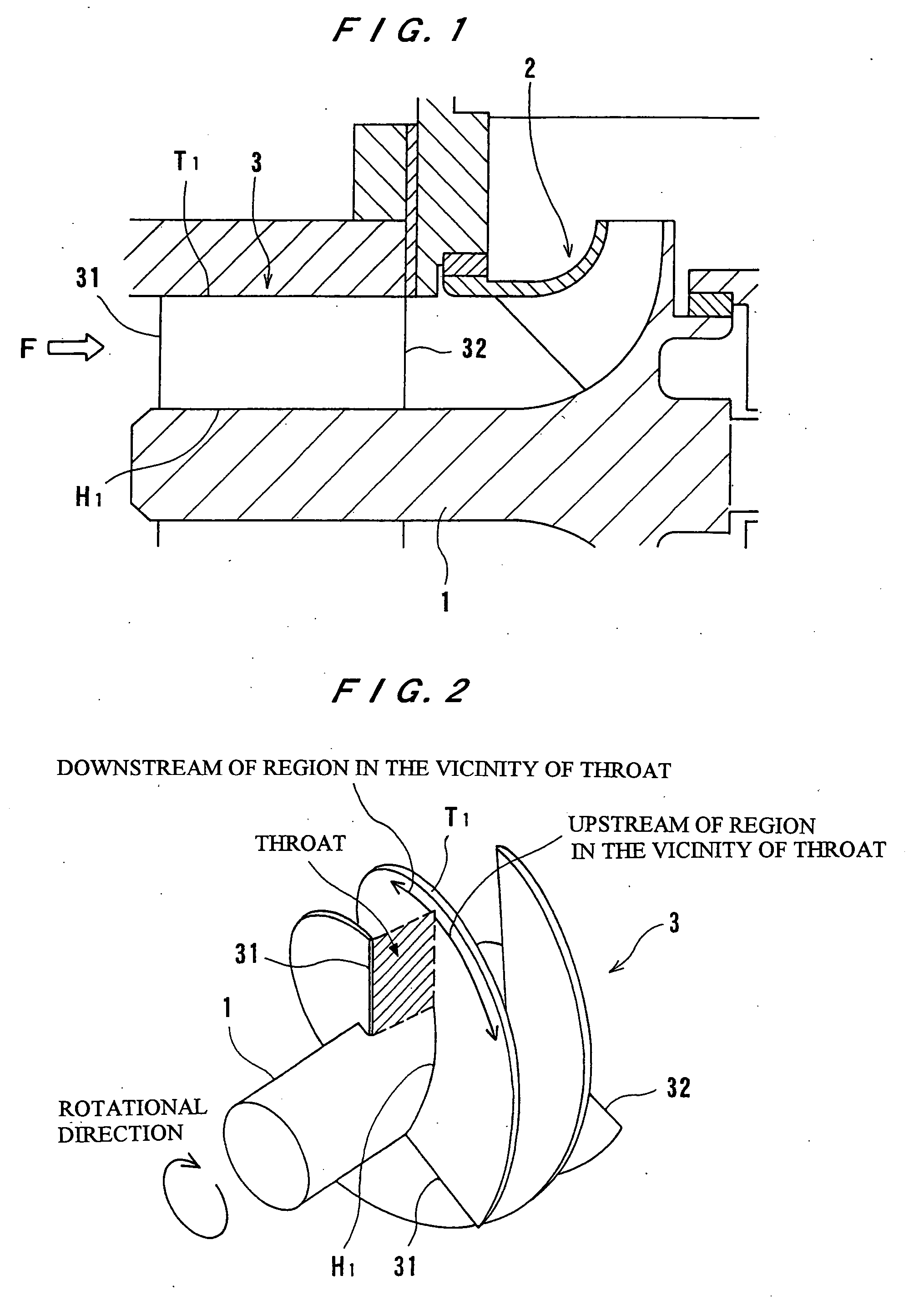
[0027] An embodiment of an inducer and a pump with an inducer according to the present invention will be described in detail below with reference to the drawings. FIG. 1 is a cross-sectional view showing a portion of a turbopump incorporating an inducer according to an embodiment of the present invention, and FIG. 2 is a perspective view of the inducer shown in FIG. 1. The turbopump shown in FIG. 1 has a rotatable shaft 1, a main impeller 2 mounted on the shaft 1, and an inducer 3 disposed upstream of the main impeller 2. The inducer 3 has an axis in alignment with the axis of the main impeller 2. When the shaft 1 rotates, the inducer 3 rotates at the same rotational speed as the main impeller 2. The inducer 3 has a plurality of blades. In FIG. 2, the inducer 3 is shown as having three blades.
[0028] A working fluid of the pump flows into the inducer 3 in the direction indicated by the arrow F in FIG. 1. The working fluid that has flowed into the inducer 3 has its pressure increased...
PUM
 Abstract
Description
Claims
Application Information