Method and apparatus for power flow management in electro-mechanical transmissions

a technology of power flow management and electromechanical transmission, applied in the direction of dynamo-electric gear control, gearing, instruments, etc., can solve the problems of affecting driving comfort, affecting the operation of the transmission system, and not always being able to use the maximum available engine power,

Active Publication Date: 2006-05-25
THE TIMKEN CO
View PDF6 Cites 161 Cited by
  • Summary
  • Abstract
  • Description
  • Claims
  • Application Information

AI Technical Summary

Problems solved by technology

Therefore, it is not always possible to use the maximum available engine power, because engine speed and load vary as the transmission moves through its limited number of fixed ratios.
Moving from one ratio to another is sometimes termed “shifting” in transmission design descriptions, and is often associated with unfavorable torque interruptions.
Such interruptions offset overall drive-line efficiency and detract from driving comfort.
Moreover, for some applications, such as agricultural and construction vehicles, an output torque interruption is extremely undesirable, more so than a momentary loss of efficiency.
In principle, a stepwise transmission cannot achieve the overall vehicle efficiency of a step-less transmission which offers an infinite number of speed ratios.
In addition, most of the CVT designs transmit torque through contacting friction surfaces and are not suitable for high-torque and high-power applications.
It consumes power and decreases transmission efficiency by generating unwanted heat within the transmission.
However, in doing so, the engine is operated at a point which is less than optimal.
However, since the mode shift in the control system of the '705 patent occurs independently of the state of the second electric machine, the problem of internal power circulation remains when the transmission is operated in reverse, and when the second electric machine continues to provide torque to the system during a mode shift.

Method used


Image

  • Method and apparatus for power flow management in electro-mechanical transmissions
  • Method and apparatus for power flow management in electro-mechanical transmissions
  • Method and apparatus for power flow management in electro-mechanical transmissions

Examples


Embodiment Construction

[0027] The following detailed description illustrates the invention by way of example and not by way of limitation. The description clearly enables one skilled in the art to make and use the invention, describes several embodiments, adaptations, variations, alternatives, and uses of the invention, including what is presently believed to be the best mode of carrying out the invention.

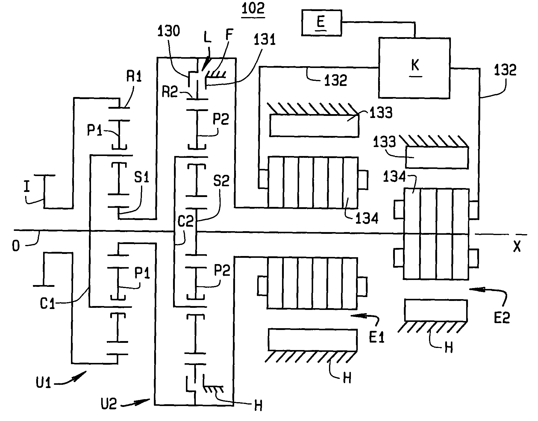
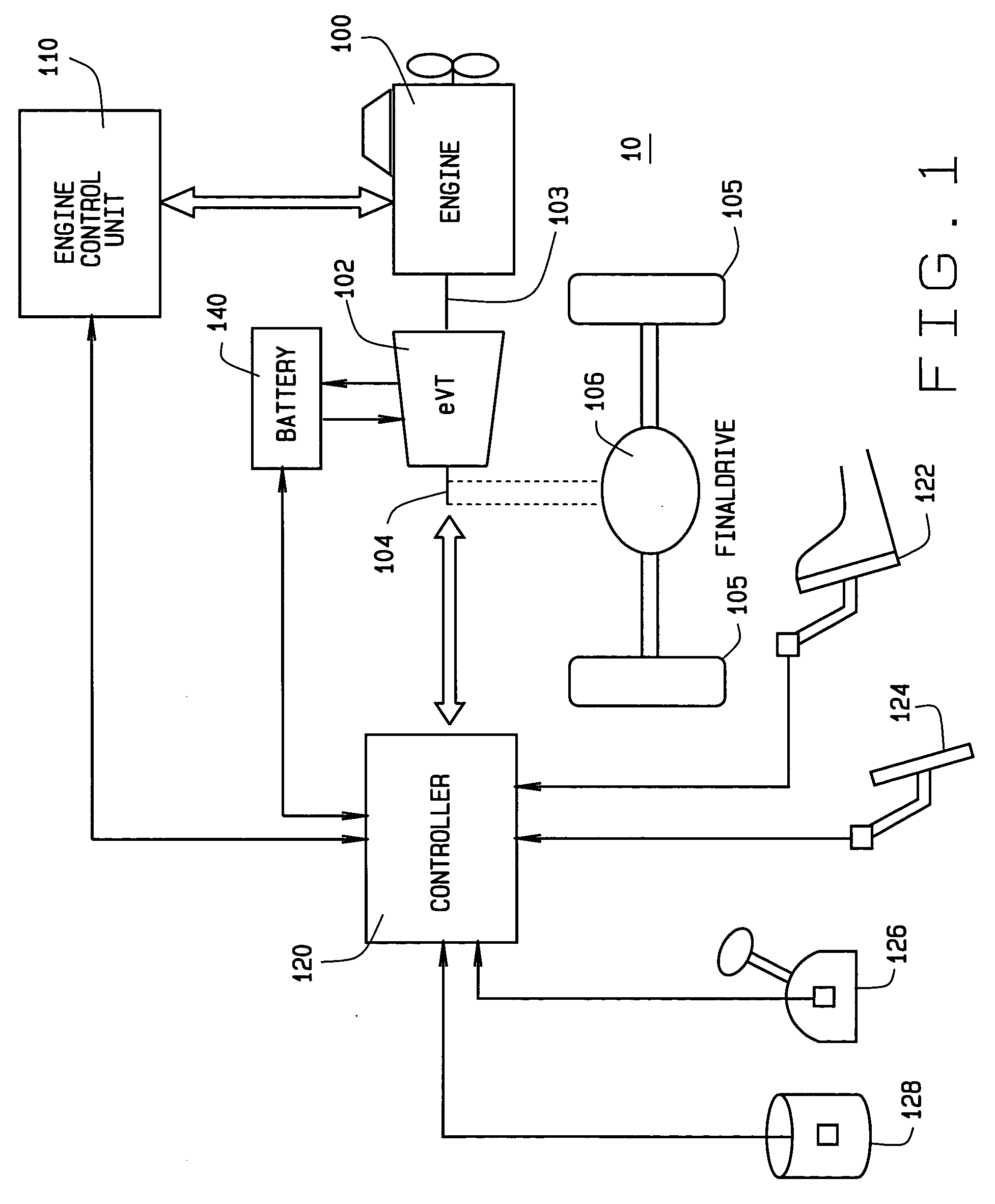
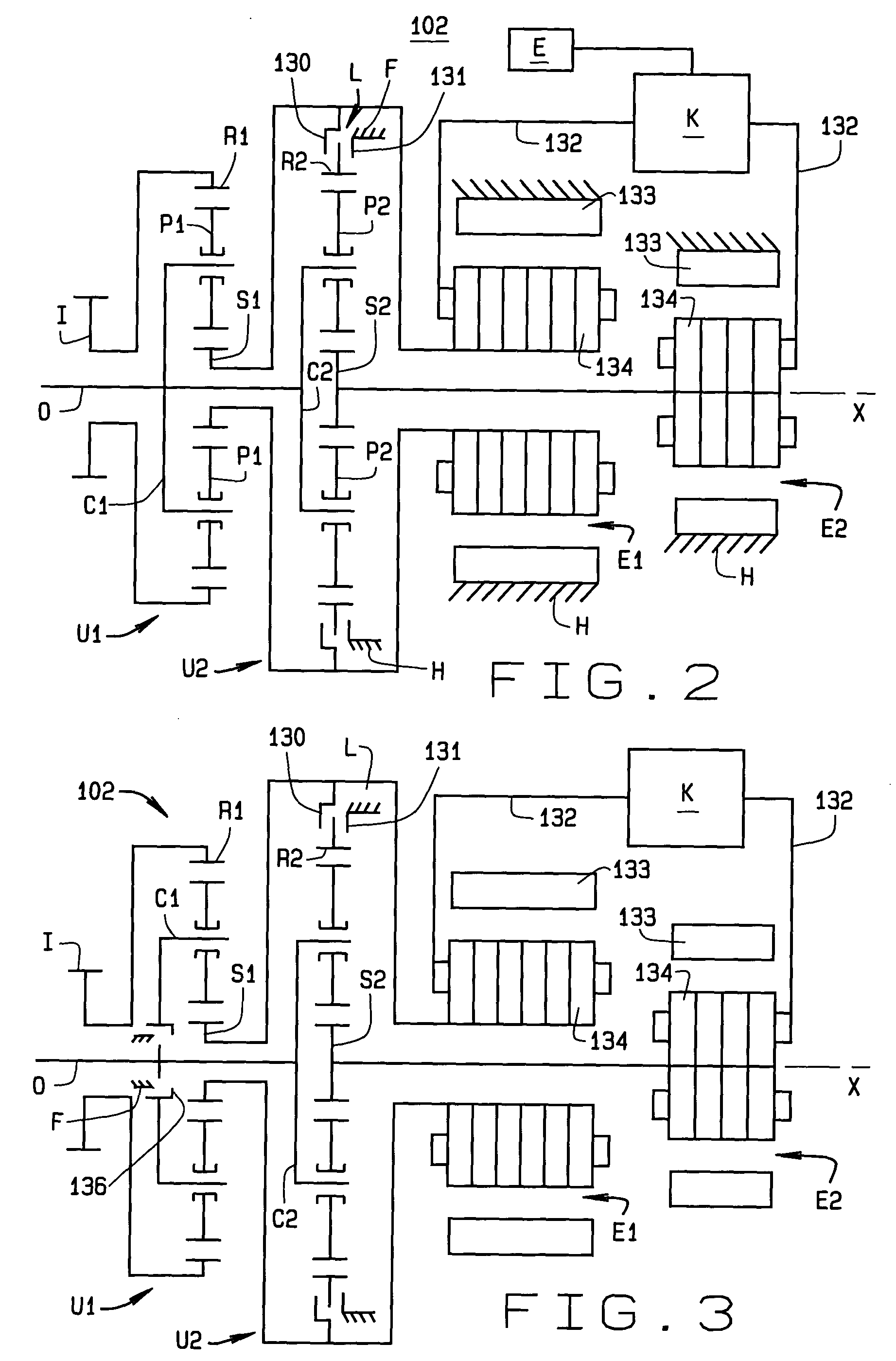
[0028] Turning first to FIG. 1, a vehicle drive system for use with the current invention is shown generally at 10. The system 10 includes an engine 100, an electro-mechanical power-split infinitely-variable transmission 102 having an input shaft 103 from the engine and a drive shaft 104 coupled to drive wheels 105 via a final drive 106. The system 10 further includes an engine control unit 110 for controlling the operation of the engine 100 and a power-train control unit 120 for communicating with the engine control unit 110 and for controlling the operation of the transmission 102 and the engine 100 b...


PUM


Abstract

A method for power management in an electro-mechanical power-split infinitely variable transmission (eVT) designed to operated within a designated speed ratio range for vehicular applications. The eVT is comprised of an input shaft coupled to the output shaft of a drive engine to receive power, a drive shaft, two electric machines, and a pair of planetary trains each having a sun member, a ring member, a set of planetary members, and a planet carrier. The eVT further contains one or more torque transfer devices to connect or disconnect members of the planetary trains for transferring torque. The drive shaft is coupled with a final drive of a vehicle for delivering or recapturing power to or from the vehicle drive wheels. The two electric machines are interconnected electronically via a power control unit and are coupled respectively with members of the planetary train. The method of power management in the eVT is selected based on the current speed and torque of the input and drive shafts, and upon the desired operating parameters.

Description

CROSS-REFERENCE TO RELATED APPLICATIONS [0001] Not Applicable. STATEMENT REGARDING FEDERALLY SPONSORED RESEARCH [0002] Not Applicable. BACKGROUND OF THE INVENTION [0003] This invention relates in general to transmissions for transmitting rotary motion and, more particularly, to a method for power flow management in an electro-mechanical output power-split and compound power-split infinitely variable transmission. [0004] The primary function of a transmission in an automotive vehicle is to convert the output speed and torque of an engine or prime mover into the speed and torque of a drive shaft to meet the specific requirements of the vehicle. In general it is desirable for this power transmission to occur with minimal power loss; that is, at high transmission efficiency. To optimize the overall power train performance, specifically the engine and transmission combination, it is also desirable to minimize engine transients and operate the engine at a power state that yields the best ...

Claims


Application Information

Patent Timeline
Patent Type & Authority Applications(United States)
IPC IPC(8): F16H3/72B60K1/02B60K6/365B60K6/445B60K6/543B60L50/16B60W10/08B60W10/10B60W20/00
CPCB60K1/02B60K6/365B60K6/445B60K6/543B60W10/08B60W10/10Y10T477/337F16H3/727F16H3/728F16H2037/102F16H2200/2007Y02T10/6239B60W20/00Y02T10/62B60W20/10
Inventor AI, XIAOLANANDERSON, SCOTT
Owner THE TIMKEN CO
Why Eureka
Try Eureka