System and method for customizing workflow using standard formats for information transfer

a workflow and information transfer technology, applied in the field of electronic communication, can solve the problems of difficulty in image storage, non-uniform output of each imaging mode, and a large number of imaging modalities producing different image formats

Active Publication Date: 2006-05-25
GENERAL ELECTRIC CO
View PDF5 Cites 11 Cited by
  • Summary
  • Abstract
  • Description
  • Claims
  • Application Information

AI Technical Summary

Problems solved by technology

A facility with imaging modalities producing different image formats is faced with a number of problems.
For example, outputs of each imaging modality may be non-uniform, which may create difficulty for storage of images from different systems onto a single media type or a single server type.
Additionally, diagnostic images associated with a single patient may be in different imaging formats, preventing easy electronic association of all diagnostic information with a single patient database record.
Furthermore, different imaging modalities with different image formats may not be able to share a single scheduling system.
Thus, different image formats created an obstacle for a centralized data management system.
While the adoption of DICOM has made possible many improvements in the way in which imaging modalities communicate information across the network of a healthcare facility, certain limitations still exist.
One limitation involves so-called “legacy” computer systems and in particular, legacy scheduling systems.
Unfortunately, the RIS of a given healthcare system may be a legacy system and not conform to DICOM.
The healthcare facility is then unable to take advantage of the standardization offered by DICOM and must find a solution involving the legacy system.
One expensive and unfavorable solution is to replace the entire scheduling system with a conforming system.
This solution is unfavorable at least because the system is otherwise

Method used


Image

  • System and method for customizing workflow using standard formats for information transfer
  • System and method for customizing workflow using standard formats for information transfer
  • System and method for customizing workflow using standard formats for information transfer

Examples


example 1

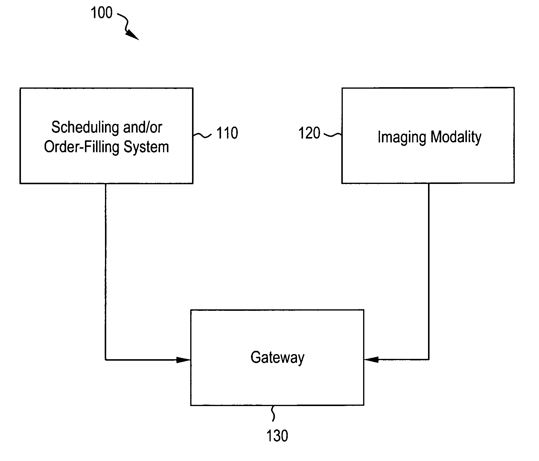
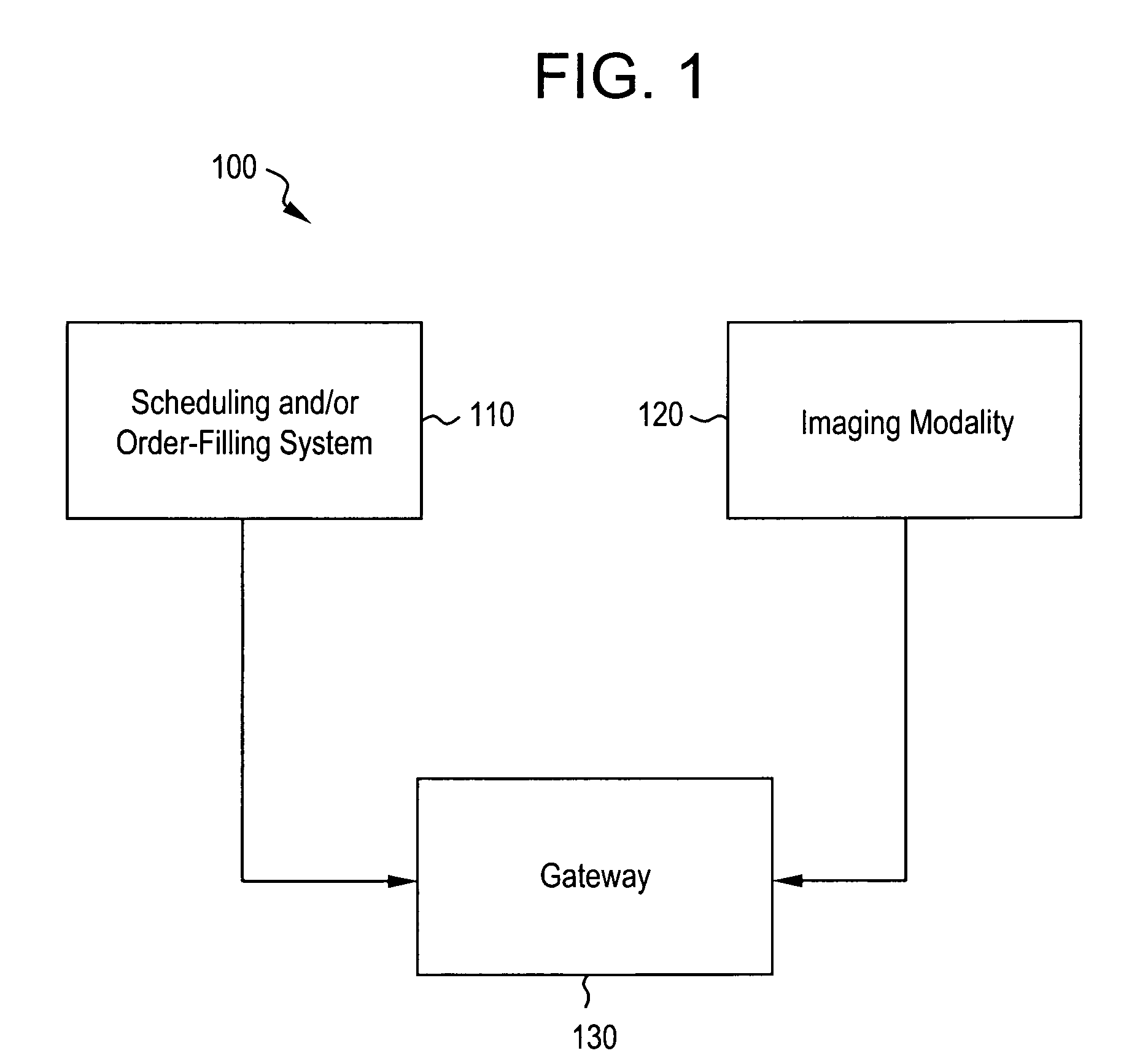
[0048] As one example, a clinic has a legacy RIS in its Radiology department. A staff member seeks to schedule a Computed Tomography (CT) imaging procedure for a newly admitted patient. The staff member interacts with the RIS to create a procedure and schedule specific to the patient. The RIS communicates the scheduling information to the gateway in a proprietary data format specific to the legacy RIS.

[0049] When the gateway receives the scheduling information, the data fields in the scheduling information are configured to be part of a WLC. For example, the field “procedure requesting department” contains the relevant data for seeking a CT scan for the Radiology department in the proprietary RIS format. The gateway codes the “procedure requesting department” data into a WLC parameter that is generic for that data field type, such as “CT Center”. The coding process configures all of the other data fields in the scheduling information into other corresponding WLC parameters.

[0050] ...


PUM


Abstract

Embodiments of the present system and method relate generally to standardized electronic communications in a healthcare setting. Certain embodiments of the system include a healthcare information acquisition and management system capable of using information that conforms to an industry standard format for information transfer, an order scheduling system capable of managing information flow within the healthcare setting, and a gateway system interconnecting the healthcare information acquisition and management system and the order scheduling system. In certain embodiments, the gateway system provides for a transfer of nonconforming information between the order scheduling system and the healthcare information acquisition and management system.

Description

BACKGROUND OF THE INVENTION [0001] Embodiments of the present system and method relate generally to electronic communications in a healthcare setting. Particularly, certain embodiments relate to providing site-specific, customizable data transfer for imaging devices using the Digital Imaging and Communications in Medicine (DICOM) information model. [0002] Clinics, hospitals, and other healthcare facilities have come to rely more and more on computers over the last several decades. In particular, healthcare facilities employ certain types of digital diagnostic imaging modalities, such as computed tomography, magnetic resonance imaging, ultrasound imaging, and X-ray imaging. Many different manufacturers developed digital diagnostic imaging modalities to gather and transmit diagnostic information, and each manufacturer employed a different, sometimes proprietary, way of handling the digital information. The method of handling information is often hardcoded into the digital diagnostic i...

Claims


Application Information

Patent Timeline
IPC IPC(8): G06Q10/00G06F17/30G16H30/20G16H40/20G16H40/67
CPCG06Q50/22G06Q50/24G16H40/67G16H40/20G16H30/20
Inventor BAO, YONGJIANVISWANATHAN, THANJAVUR N.LACROIX, MARIE-JOSERAI, KHALDOUN A.SORRENTINO, ANDREW
Owner GENERAL ELECTRIC CO
Why Eureka
Try Eureka