Industrial two-layer fabric

a two-layer fabric and fabric technology, applied in the field of industrial two-layer fabric, can solve the problems of warp protruding from the lower surface side surface, not suited to applications requiring wear resistance and rigidity, and easy to be worn away, so as to improve the surface property, run stability and water drainage, and improve the effect of wear resistan

Active Publication Date: 2006-06-01
NIPPON FILCON
View PDF31 Cites 21 Cited by
  • Summary
  • Abstract
  • Description
  • Claims
  • Application Information

AI Technical Summary

Benefits of technology

[0005] By forming this fabric with yarns of a small diameter, it has a small thickness and becomes suited for manufacture of tissue paper, but not suited for applications requiring wear resistance and rigidity. Even if a lower surface side weft having a large diameter is used for a fabric of such a design, it is not flexible so that a warp protrudes from the lower surface side surface and is easily worn away.
[0007] An object of the present invention is to provide an industrial two-layer fabric capable of satisfying all the properties required for industrial fabrics such as surface property, wear resistance, rigidity, running stability and water drainage property.
[0011] The industrial two-layer fabric according to the present invention is able to have improved wear resistance, surface property, rigidity, running stability and water drainage property by disposing a pair of warp binding yarns which complement an upper fabric design and a lower fabric design respectively, forming the lower surface side fabric while applying to two warps adjacent to each other the same design that they pass over and under one lower surface side weft, and forming a long crimp of a lower surface side weft on the lower surface side surface.

Problems solved by technology

By forming this fabric with yarns of a small diameter, it has a small thickness and becomes suited for manufacture of tissue paper, but not suited for applications requiring wear resistance and rigidity.
Even if a lower surface side weft having a large diameter is used for a fabric of such a design, it is not flexible so that a warp protrudes from the lower surface side surface and is easily worn away.
Thus, in industrial fabrics using a warp binding yarn, those capable of satisfying all of the wear resistance, surface property, rigidity, running stability and water drainage property have not yet been developed.

Method used


Image

  • Industrial two-layer fabric
  • Industrial two-layer fabric
  • Industrial two-layer fabric

Examples


example 2

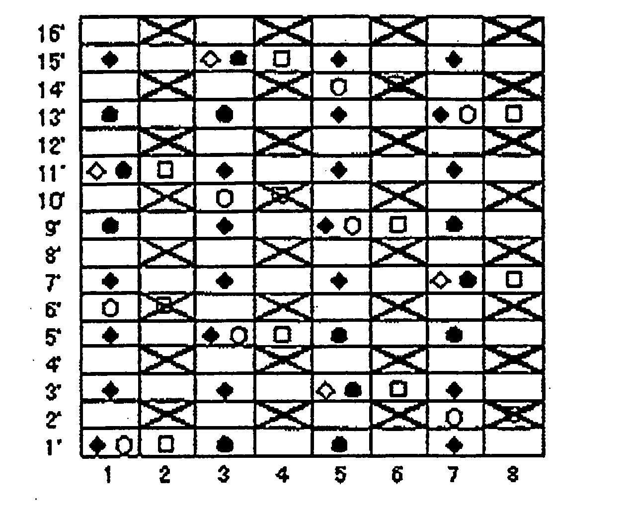
[0064] The fabric obtained in Example 2 is a 16-shaft two-layer fabric in which a pair of an upper surface side warp and a lower surface side warp and a pair of warp binding yarns are alternately arranged. A 1 / 3 twill weave design is adopted as the upper surface side surface design, while a 3 / 1 design is adopted as the lower surface side surface design. Upper surface side wefts and lower surface side wefts are arranged at 4:3, which is similar to Example 1.

[0065] In the design diagram of FIG. 4, indicated by numerals 1, 3, 5 and 7 are pairs of two warp binding yarns arranged vertically, and indicated by numerals 2, 4, 6 and 8 are pairs of an upper surface side warp and a lower surface side warp. Pairs of warps and pairs of warp binding yarns are arranged alternately.

[0066] The fabric of this example is different from that of Example 1 in the upper surface side surface design. Described specifically, an upper surface side warp and an upper surface side weft are interwoven to form a...

example 3

[0070] The fabric obtained in Example 3 is a 16-shaft two-layer fabric in which three pairs of an upper surface side warp and a lower surface side warp are arranged relative to a pair of warp binding yarns. This fabric is formed by alternately arranging, for warps of the upper surface side design, a 1 / 1 plain weave design and a 2 / 2 level weave design and, for the lower surface side design, a 1 / 3 design. Upper surface side wefts and lower surface side wefts are arranged at 4:3, similar to that of Example 1.

[0071] In the design diagram of FIG. 7, indicated by numerals 1 and 5 are pairs of two warp binding yarns arranged vertically, while indicated by numerals 2, 3, 4, 6, 7, and 8 are pairs of an upper surface side warp and a lower surface side warp. The pairs of warp binding yarns and the pairs of warps are arranged at a ratio of 1:3.

[0072] Upper surface side warps are woven alternately with upper surface side wefts and some of the upper surface side warps form a 1 / 1 plain weave des...

example 4

[0076] The fabric obtained in Example 4 is a 12-shaft two-layer fabric in which a pair of an upper surface side warp and a lower surface side warp and a pair of warp binding yarns are alternately arranged. This fabric is obtained by employing a 1 / 2 twill weave design for the upper surface side surface design and a 2 / 1 design for the lower surface side surface design. Upper surface side wefts and lower surface side wefts are arranged at 1:1.

[0077] In the design diagram of FIG. 10, indicated by numerals 1, 3, 5 are pairs of two vertically-arranged warp binding yarns, while indicated by numerals 2, 4 and 6 are pairs of an upper surface side warp and a lower surface side warp. Pairs of warp binding yarns and pairs of warps are arranged at 1:1.

[0078] Upper surface side warps are woven with upper surface side wefts to form a 1 / 2 twill weave design on the upper surface side surface. Warp binding yarns forming a pair alternately appear on the upper surface side surface, function as one wa...


PUM


Abstract

An industrial two-layer fabric composed of an upper surface side fabric having an upper surface side warp and an upper surface side weft and a lower surface side fabric having a lower surface side warp and a lower surface side weft, the upper surface side warp and lower surface side warp being arranged vertically and constituting a pair, and the upper surface side fabric and lower surface side fabric being bound with a yarn in a warp direction. The lower surface side fabric is made of a repeating design unit in which one of warp binding yarns constituting a pair to be woven with an upper surface side weft and a lower surface side weft or a lower surface side warp passes under one lower surface side weft and then passes over a plurality of lower surface side wefts; a warp on one adjacent side to the above-described warp has the same design and passes over and under the same lower surface side wefts. A complete design repeating unit of the lower surface side fabric is formed by shifting the design of a set of these two warps and then arranging the shifted design one after another; and a lower surface side weft has a design in which the weft passes over two successive warps and then passes under a plurality of warps to form a long crimp on the lower surface side surface.

Description

TECHNICAL FIELD OF THE INVENTION [0001] The present invention relates to an industrial two-layer fabric using a warp binding yarn, which can satisfy the physical properties necessary for industrial fabrics such as wear resistance, surface property, rigidity, running stability and water drainage property. BACKGROUND OF THE INVENTION [0002] Fabrics obtained by weaving warps and wefts have conventionally been used widely as an industrial fabric. They are, for example, used in various fields including papermaking wires, conveyor belts and filter cloths and are required to have fabric properties suited for the intended use or using environment. Of such fabrics, a papermaking wire used in a papermaking step for removing water from raw materials by making use of the network of the fabric must satisfy a severe demand. There is therefore a demand for the development of fabrics which do not transfer a wire mark of the fabric and therefore have excellent surface property, have enough wear resi...

Claims


Application Information

Patent Timeline
Patent Type & Authority Applications(United States)
IPC IPC(8): D03D25/00
CPCD21F1/0036Y10T442/3195
Inventor NAGURA, HIROYUKIUEDA, IKUOMURAKAMI, MASAKAZU
Owner NIPPON FILCON
Why Eureka
Try Eureka