

Railway car coupler knuckle having improved bearing surface
a technology for coupler knuckles and railways, which is applied in the field of railway freight car couplers, can solve the problems of difficult manufacturing of coupler knuckle castings, delayed trains, and premature failure, and achieves the effects of minimizing stress set up, improving bearing surface, and prolonging life cycl
- Summary
- Abstract
- Description
- Claims
- Application Information
AI Technical Summary
Benefits of technology
Problems solved by technology
Method used
Image

Examples
Embodiment Construction
[0030] Knuckle coupler castings and methods of casting knuckle coupler castings are described herein and illustrated in FIGS. 1-17. The knuckle coupler castings have enhanced bearing surfaces and / or enhanced lock wall surfaces. The enhanced bearing surfaces can reduce instances of point to point contact between engaged knuckles, and can result in knuckles having reduced failure rates and greater life span predictability. Moreover, a single core can be used to form the bearing and lock wall surfaces to provide improved relative positioning between the two surfaces.
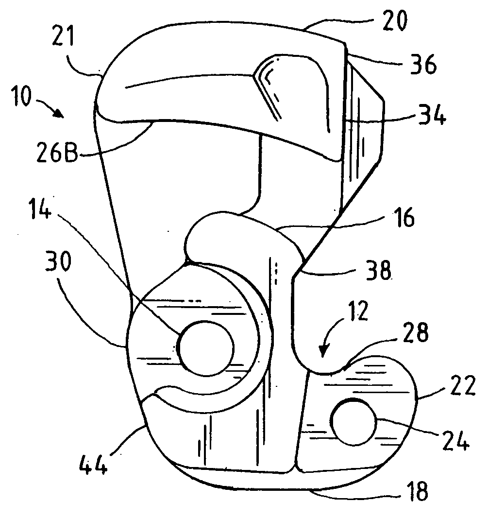
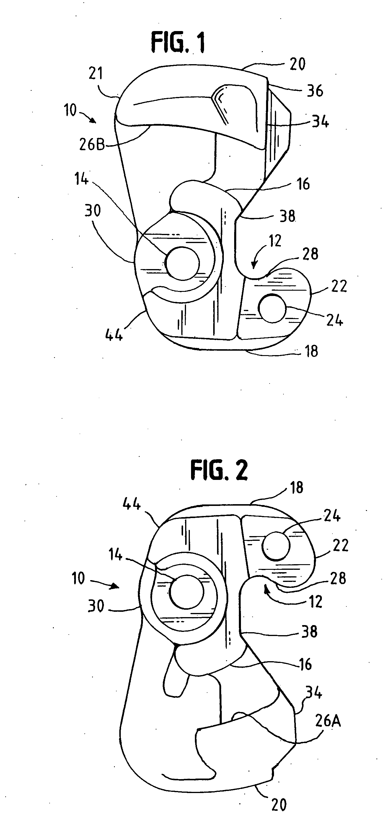
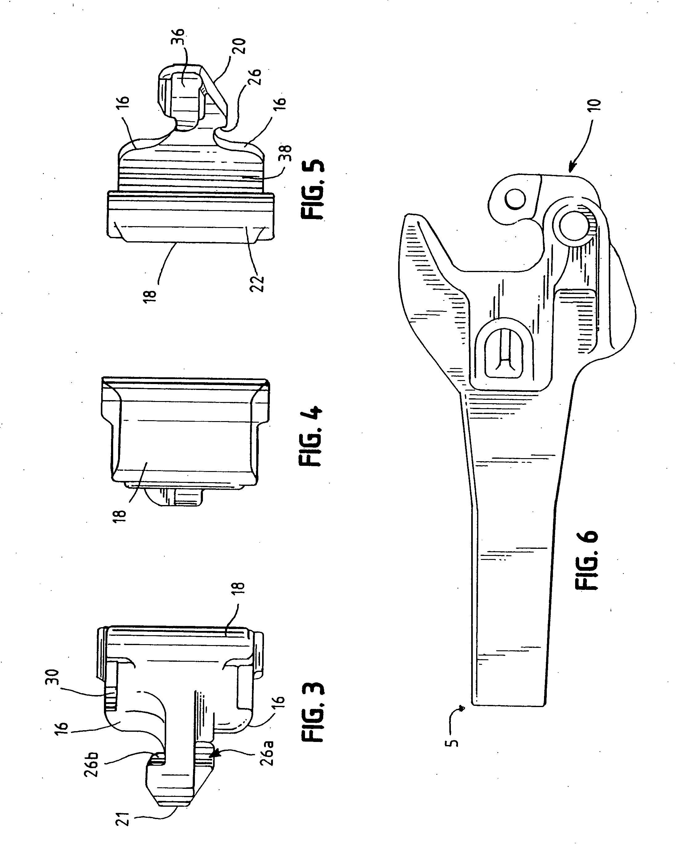
[0031] A coupler knuckle casting 10 is configured for use with a typical coupler 5, as illustrated in FIG. 6, for a railway freight car (not shown). The coupler knuckle casting 10 has an improved or enhanced bearing surface area 12.
[0032] The coupler knuckle casting 10 having the enhanced bearing surface area 12 includes a tail section 20, a hub section 30, and a front face section 18, as illustrated in FIGS. 1-5. The hub...
PUM
| Property | Measurement | Unit |
|---|---|---|
| Angle | aaaaa | aaaaa |
| Ratio | aaaaa | aaaaa |
| Radius | aaaaa | aaaaa |
Abstract
Description
Claims
Application Information