Current programming apparatus and matrix type display apparatus

a display apparatus and current programming technology, applied in the direction of instruments, static indicating devices, etc., can solve the problem that the operation of writing an image data current cannot be stably performed in each pixel circuit, and achieve the effect of suppressing the parasitic capacitance of a data line and stabilizing the writing operation of curren

Inactive Publication Date: 2006-06-01
CANON KK
View PDF13 Cites 32 Cited by
  • Summary
  • Abstract
  • Description
  • Claims
  • Application Information

AI Technical Summary

Benefits of technology

[0042] According to the present invention, the influences of the parasitic capacitanc...

Problems solved by technology

When a conventional current writing type pixel circuit is used, there is a case where a...

Method used


Image

  • Current programming apparatus and matrix type display apparatus
  • Current programming apparatus and matrix type display apparatus
  • Current programming apparatus and matrix type display apparatus

Examples


first embodiment

[0049]FIG. 3 is a configuration diagram showing the configuration of an active matrix field emission display apparatus according to the present invention.

[0050] In FIG. 3, a reference numeral 1 denotes a pixel circuit unit composed of pixel circuits arranged in a matrix. In the pixel circuit unit 1, electroluminescent elements and circuits driving the electroluminescent elements are arranged in a matrix, and the pixel circuit unit 1 includes scanning signal lines connecting them in row directions and data lines connecting them in column directions.

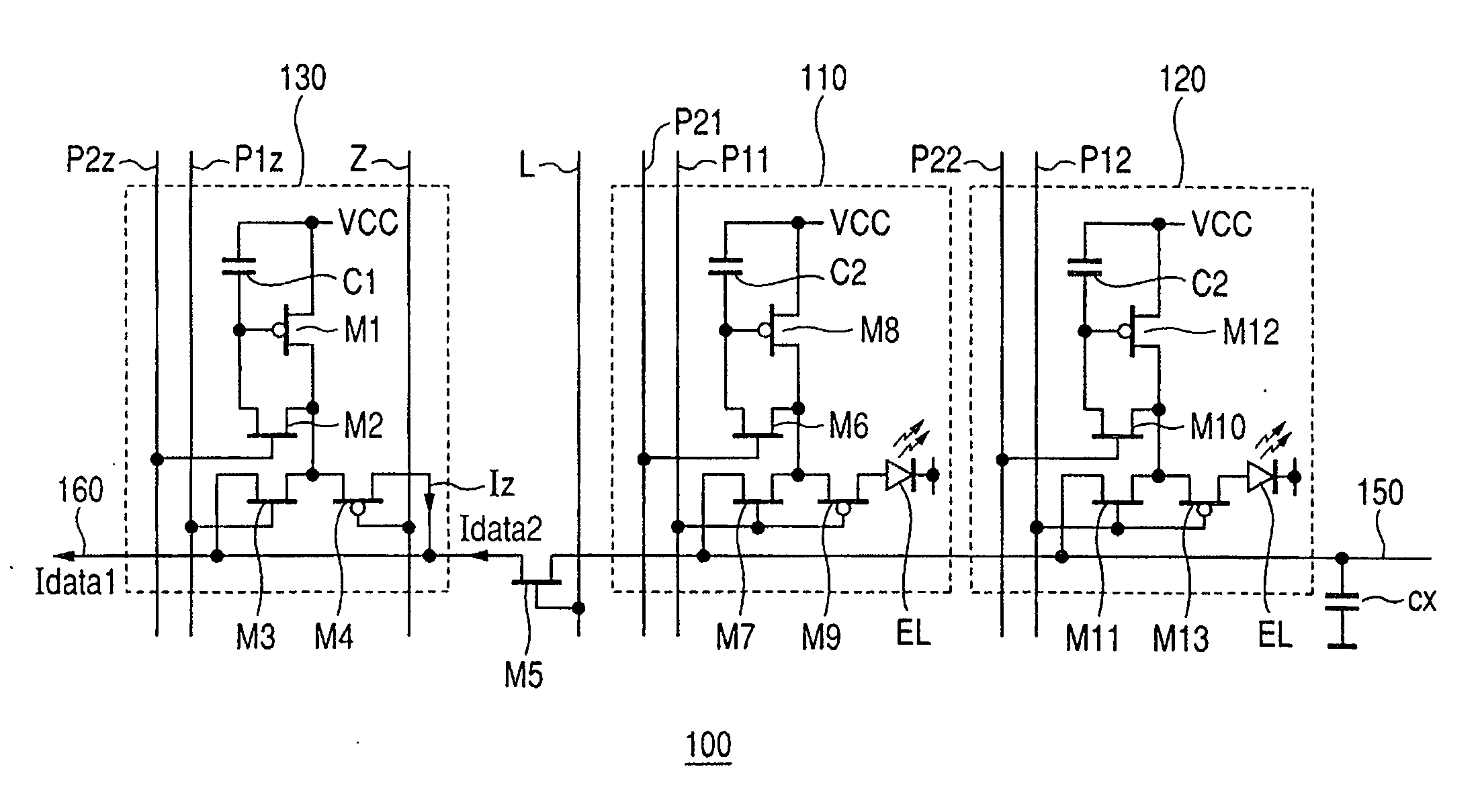
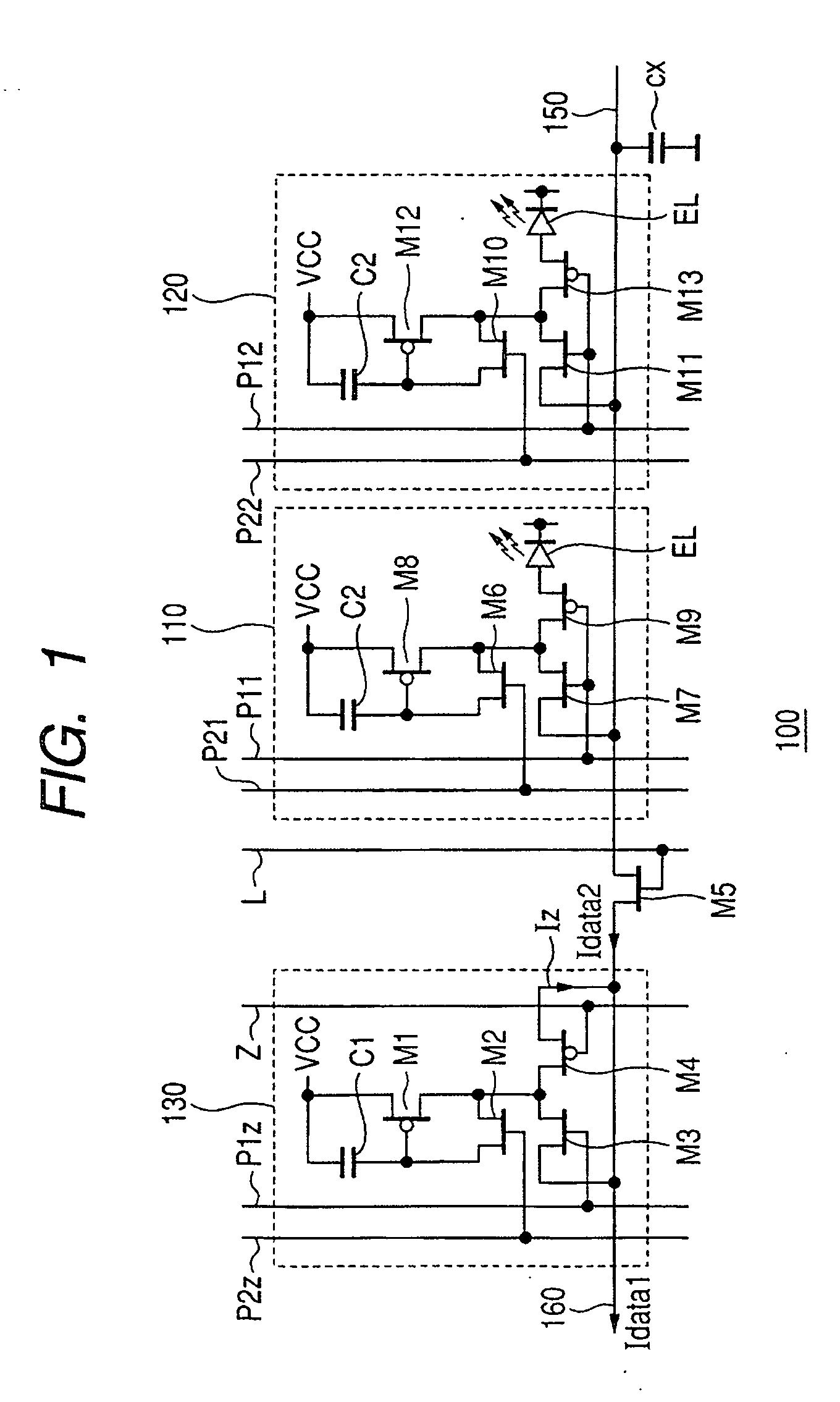
[0051] A reference numeral 2 denotes data line switches performing the separation and the connection of the data lines. A reference numeral 3 denotes a zero current setting circuit provided to each pixel circuit column into which a current is written based on a zero setting current (a reference current). A reference numeral 4 denotes column current control circuits supplying line-sequential data line current signals Idata and zero settin...

second embodiment

[0078]FIG. 5 is a diagram showing an example of the configuration of the current programming circuit according to a second embodiment of the present invention. In the present embodiment, the configuration of the zero current setting circuit 130 is more simplified by omitting the nMOS transistor M3 and the pMOS transistor M4, and by connecting the PMOS transistor M1 to the data line directly. In such a configuration, also the effect similar to that of the first embodiment also can be acquired.

[0079] Although the active matrix type display apparatus using the current based driven display elements is picked up to be described as an example of using the current programming apparatus according to the present invention above, the current programming apparatus according to the present invention can be applied to a use, as long as the use is that using a current setting circuit holding a current to be flown into a data line as the gate-source voltage of a transistor. The use of the current...


PUM


Abstract

A current programming apparatus includes a current source; a plurality of first circuits to which data currents are supplied through a data line, the first circuits commonly connected with the data line; a second circuit having a terminal connected to the current source; a switch connecting or breaking the second circuit with or from the data line, wherein the current source generates a predetermined current to supply the generated current to the second circuit through the terminal while the switch is off, whereby the value of the predetermined current is written in the second circuit, and wherein the current source generates a current based on data, and the second circuit generates a current based on the written value of the predetermined current, and a difference current between the current generated by the current source and the current generated by second circuit is supplied to the first circuits through the data line while the switch is on, whereby the value of the current is written in the first circuits as the value of the data current. The influence of parasitic capacitance of the data line can be suppressed to stabilize the writing operation of the current.

Description

BACKGROUND OF THE INVENTION [0001] 1. Field of the Invention [0002] The present invention generally relates to a current programming apparatus, a matrix type display apparatus, a current programming method, and a drive method of a matrix type display apparatus, and more particularly to ones suitably used for an active matrix type display apparatus using current based driven display elements. [0003] 2. Description of Related Art [0004] In an active matrix type display apparatus using electroluminescent elements, a current writing type circuit writing a drive current of a light emitting device into the drive circuit of each pixel to make the drive circuit store the drive current has been used. In the present specification, such an operation of writing a drive current into each pixel of a matrix type display apparatus to make the drive circuit store the drive current is called as current programming, and the circuit for the current programming is called a current programming circuit. [...

Claims


Application Information

Patent Timeline
IPC IPC(8): G09G3/30
CPCG09G3/325G09G2300/0861G09G2320/029G09G2320/043
Inventor YAMASHITA, TAKANORIISEKI, MASAMIKAWANO, FUJIO
Owner CANON KK
Why Eureka
Try Eureka