System for draining and irrigating athletic fields

Inactive Publication Date: 2006-06-01
SMYERS WILLIAM H JR
View PDF8 Cites 6 Cited by
  • Summary
  • Abstract
  • Description
  • Claims
  • Application Information

AI Technical Summary

Problems solved by technology

The safety of players can be jeopardized in case heads are not installed deep enough or if they occasionally don't fully retract and a player falls knee-first on to a sprinkler.
A ball hitting the location of a sprinkler head may bounce at an unexpected angle, or a player's foot may twist when planting his foot at a sprinkler location.
A leaky sprinkler may result in a hazardous muddy soft spot in the field 2.
There are problems of obtaining uniform coverage since the heads typically give circular patterns or sectors thereof, so that there are inevitably either some areas that don't get enough water or some that get too much from overlapping patterns.
Water is lost to evaporation in the air before it even gets to the grass.
The system requires substantial water pressure in order to spray a significant distance from the heads, so the needed strength of the piping increases the cost.
Often the watering is limited to a few pre-dawn hours, and the large flows require large pipes, thus further increasing system cost.
There is a continuing maintenance cost of figuring on a daily or weekly basis in response

Method used


Image

  • System for draining and irrigating athletic fields
  • System for draining and irrigating athletic fields
  • System for draining and irrigating athletic fields

Examples


Embodiment Construction

[0034] The following description of a typical system for a 390 by 240 ft. soccer field uses exemplary dimensions so that a typical configuration can be readily visualized. Naturally those skilled in the art can vary these numbers over wide ranges depending upon the application, while still making use of the primary features of the invention.

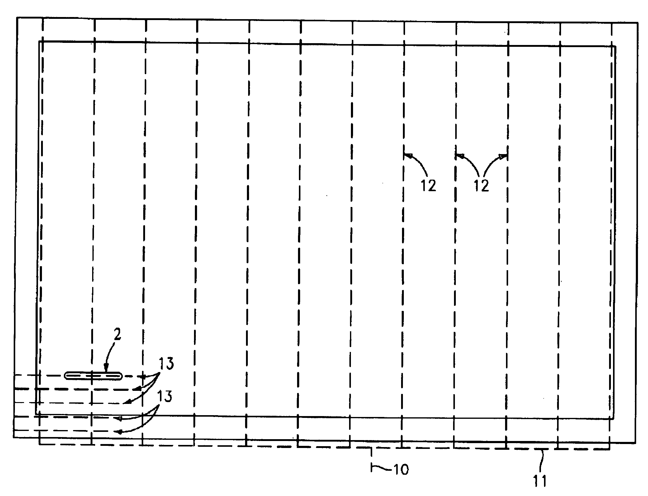
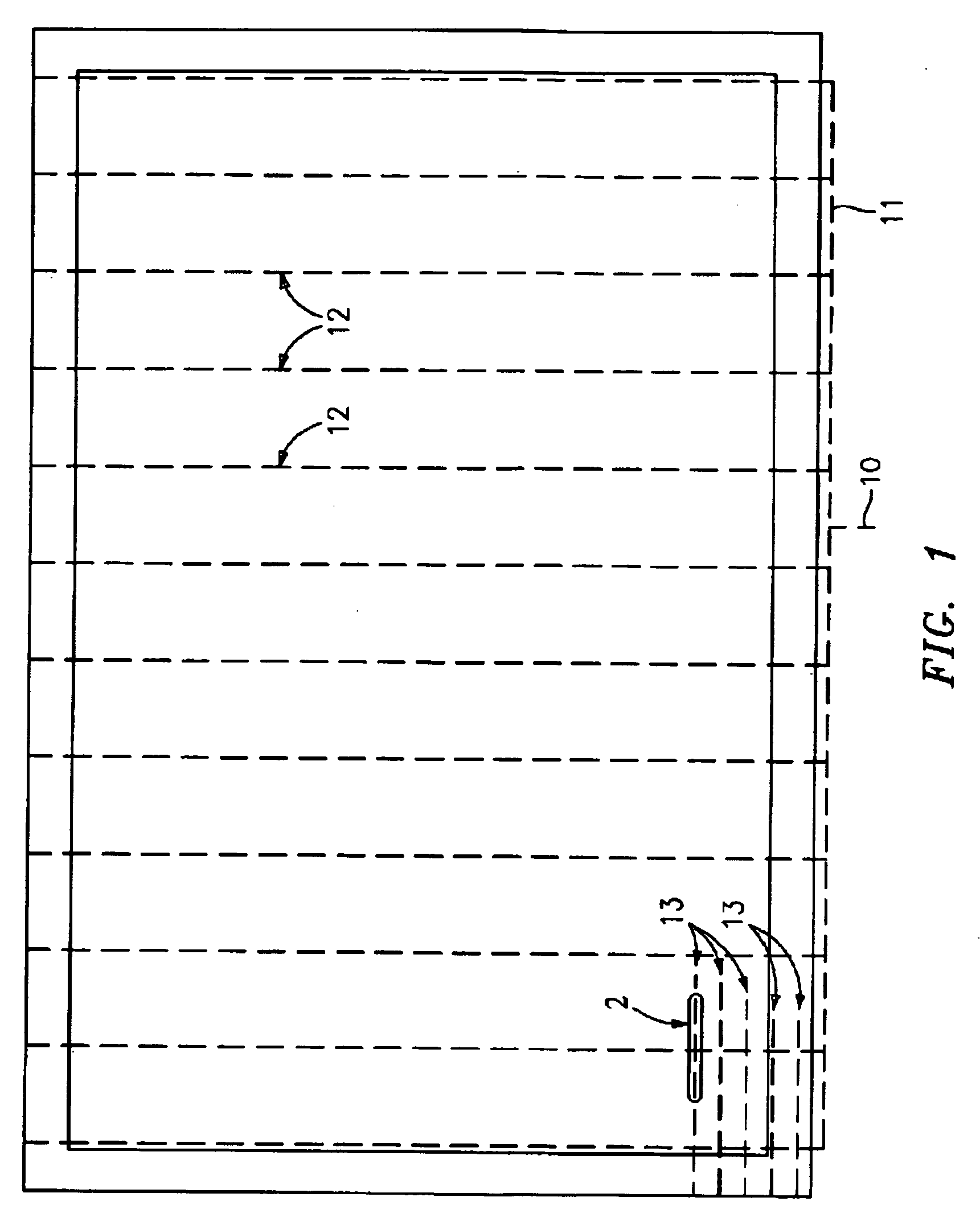
[0035]FIG. 1 shows an exit 10, typically a pipe or ditch, to conduct drainage water off site. It receives discharge from collector 11, also typically a pipe or ditch. Collector 11 receives discharge in turn from 12 horizontal trenches 12 in a lower layer. The trenches are 240 ft. long and spaced 32.5 ft. apart, 3 of which are labeled as examples. There are 30 horizontal slots 13 in an upper layer, only 5 of which are partially shown and labeled to avoid clutter in the figure. The slots are 390 ft. long, and are spaced 8 ft. apart. They intersect the trenches at an angle, in this case 90 degrees, and water can drain from the slots into the trench...


PUM


Abstract

A water control system is described for providing drainage and/or irrigation of an athletic field or other surface without using thick beds of sand and gravel, and without removing existing turf or buying new turf. A lower layer of the system is a series of typically parallel, generally horizontal trenches, widely spaced and containing coarse gravel and optional perforated pipes on a gentle slope. The downstream ends of the trenches join with a collector which drains water away from the site. An upper layer of the system comprises another set of usually narrower, shallower, and more closely spaced parallel and upwardly open slots filled with finer porous media such as sand, and intersecting the trenches at an angle such as ninety (90) degrees. Porous tubing may be used at a slight slope along the bottom of these slots to conduct water to openings in the tubing at the intersections. A thin layer of porous media, often mixed with other materials such as compost or peat, is spread on top and raked such that grass can grow through it. This layer conducts water horizontally to the nearest slot in order to drain surface water rapidly even if the original turf has very low permeability. During dry seasons a water level can be maintained in the collector and hence in the media of the slots for irrigation, thus eliminating the need for a sprinkler system. During rainy seasons, the collector may be left open for rapid drainage.

Description

BACKGROUND OF INVENTION Irritation [0001] Many approaches have been used for both irrigating and draining surfaces such as athletic fields. Irrigation systems typically comprise a network of underground piping connected to retractable sprinkler heads. Such a system has many disadvantages: [0002] 1. The safety of players can be jeopardized in case heads are not installed deep enough or if they occasionally don't fully retract and a player falls knee-first on to a sprinkler. A ball hitting the location of a sprinkler head may bounce at an unexpected angle, or a player's foot may twist when planting his foot at a sprinkler location. A leaky sprinkler may result in a hazardous muddy soft spot in the field [0003] 2. There are problems of obtaining uniform coverage since the heads typically give circular patterns or sectors thereof, so that there are inevitably either some areas that don't get enough water or some that get too much from overlapping patterns. [0004] 3. Water is lost to ev...

Claims


Application Information

Patent Timeline
IPC IPC(8): A01G25/00
CPCA01G25/06E01C13/083
Inventor SMYERS, WILLIAM H. JR.
Owner SMYERS WILLIAM H JR
Why Eureka
Try Eureka