Runner for francis type hydraulic turbine

a technology of hydraulic turbines and runners, applied in the field of hydraulic turbine runners, can solve the problems of increasing the cost of the manufacture of runners, and reducing the static and dynamic stress concentration of runners, so as to reduce the cost of manufacture, reduce the volume of blades, and reduce the effect of static and dynamic stress concentration

Inactive Publication Date: 2006-06-01
GENERAL ELECTRIC CANADA MISSISSAUGA
View PDF5 Cites 13 Cited by
  • Summary
  • Abstract
  • Description
  • Claims
  • Application Information

AI Technical Summary

Benefits of technology

[0006] The tip extension portion reduces both static and dynamic stress concentrations by having the shape of the blade at the outlet edge adjacent the band as a tip extension portion. This tip extension portion for the blade is less costly to manufacture than trying to build the material at the corner or thicken weld fillets since this tip extension portion adds minimal blade volume and results in significant stress reduction. Since the tip extension portion is built into the blade at the hydraulic design stage the weld fillet size remains small, there is no negative impact on hydraulic performance or cavitation behavior. It is further envisaged that existing runner blades can have their shape altered at the junction portion between the blade outlet edge portion and the band to provide the tip extension portion provided the outlet edge is continuous between the crown and the band.

Problems solved by technology

This phenomenon may result in blade erosion and cracking adjacent the band.
However, thickening of the blade adjacent the junction with the band must be substantial in size to relieve the stress concentration and this results in a more costly solution.
Increasing the weld fillet size also adds cost to the manufacture of the runner and can cause problems with distortion of the runner due to the increase in weld material deposited.
Both these traditional solutions typically add uneven surface contours to the blade that result in negative impacts on hydraulic performance in both efficiency and cavitation behavior of the runner.

Method used


Image

  • Runner for francis type hydraulic turbine
  • Runner for francis type hydraulic turbine
  • Runner for francis type hydraulic turbine

Examples


Embodiment Construction

[0019] The present invention relates to hydraulic machines and in particular to improvements in runners for Francis-type machines.

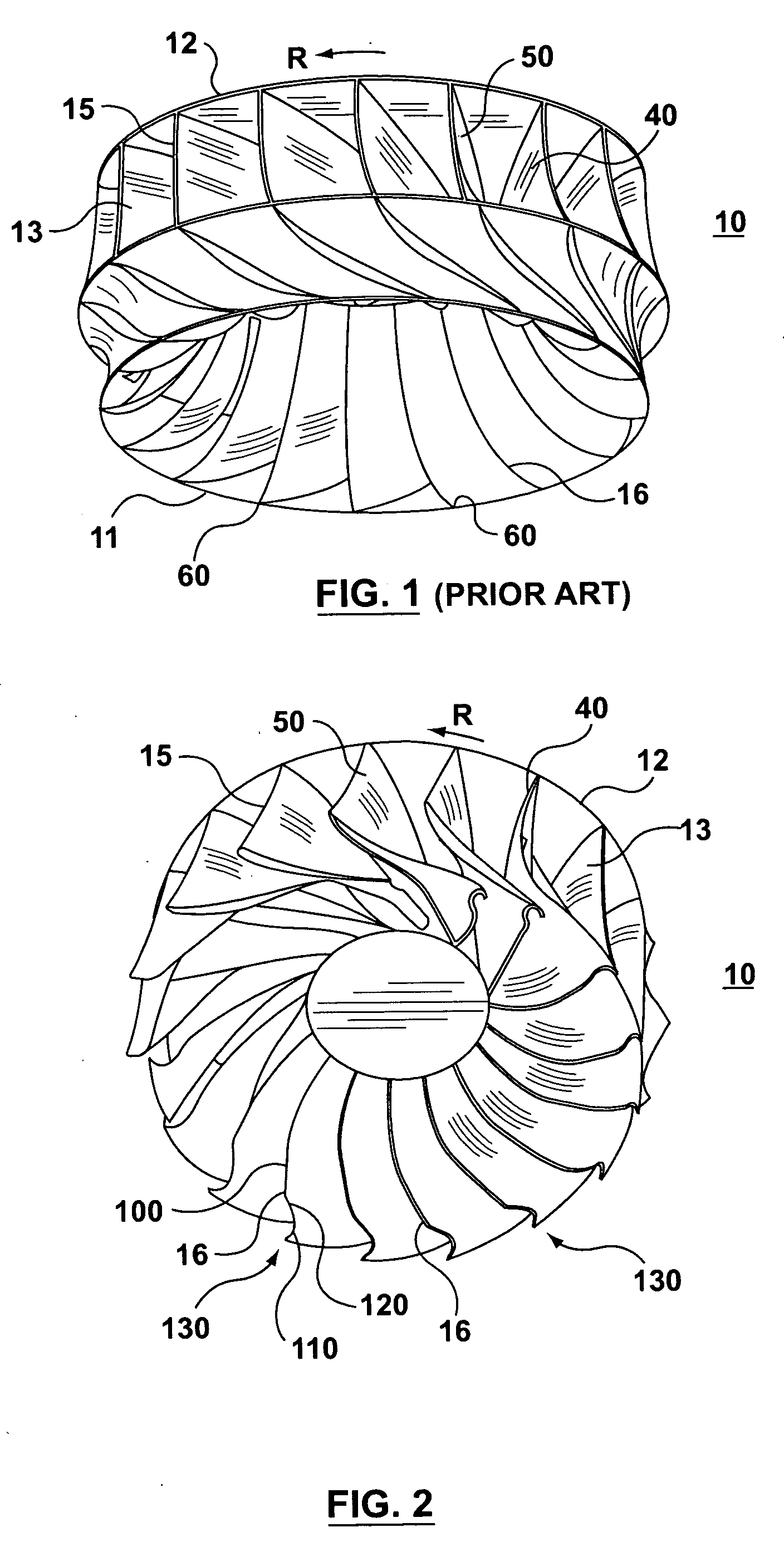
[0020]FIG. 1 schematically shows a known prior art runner 10 having a band or ring 11 and a hub or crown 12 to which the blades 13 are attached in a usual manner. The runner 10 rotates in the direction of arrow R such that each blade 13 defines a suction surface 40 leading in the direction of rotation and a pressure surface 50 trailing in the direction of rotation. It should be noted that in the blade configuration of FIG. 1, each of the blades 13 has a corner 60 adjacent where the outlet edge 16 of the blade 13 is attached or joined to the band 11. It is this corner 60, of about 90 degrees in FIG. 1, that blade 13 is subject to the static and dynamic stress concentrations mentioned above.

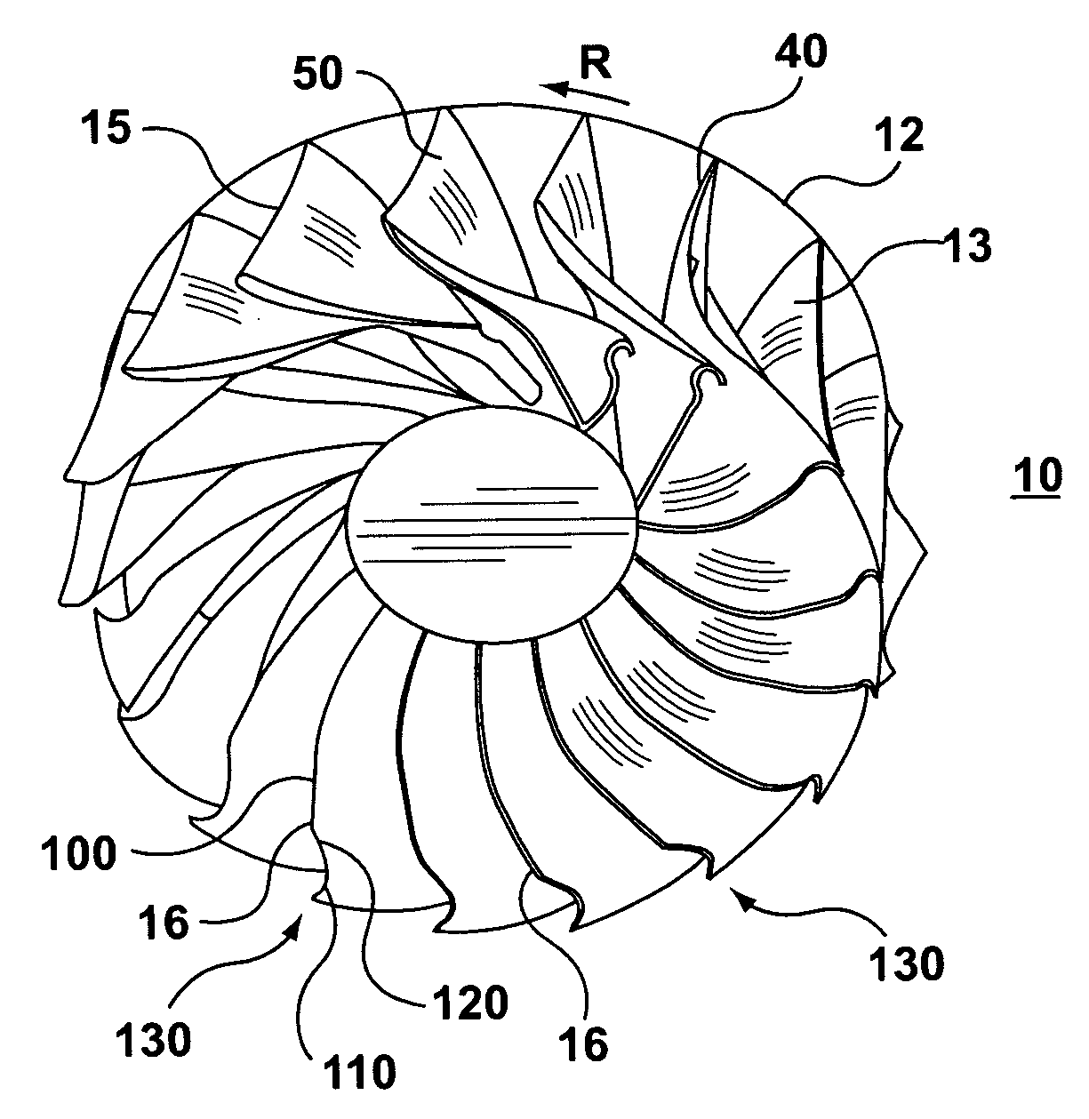
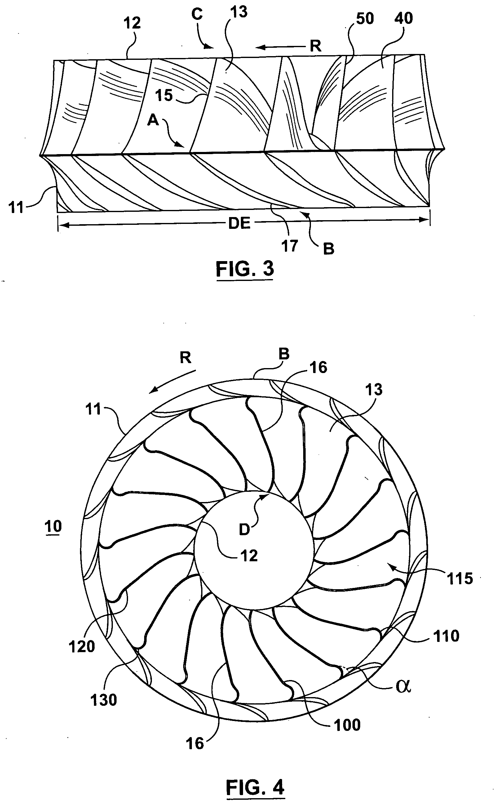
[0021] Referring to FIGS. 2 to 4, the runner 10, according to the invention is also shown with a crown 12. For clarity the actual surrounding ring or band has been omi...


PUM


Abstract

There is disclosed a runner for a Francis-type hydraulic turbine where each runner blade has a outlet edge comprising a deflected edge portion. The deflected edge portion is located adjacent to the junction or attachment point of the outlet edge to the band of the runner to define a stress reducing tip extension portion of the blade adjacent the band. This tip extension portion reduces stress concentration adjacent where the outlet edge joins the runner band.

Description

BACKGROUND OF THE INVENTION [0001] The present invention relates to hydraulic machines and in particular to improvements in runners for Francis-type machines. [0002] Conventional Francis-type runners are composed of a crown with a concentric band or ring and an array of blades extending between and interconnecting the crown with the ring. The runner is rotated about the axis of the crown by the action of water passing through a plurality of flow paths formed between each pair of adjacent blades in the array of blades. Each of the blades has a flow dividing edge which defines the line of demarkation between a suction surface leading in the direction of rotation and a trailing pressure surface trailing in the direction of rotation. This edge, at the inlet of the blades, is normally oriented to slope from the band toward the crown to advance in the direction of rotation of the runner. [0003] More recently, WO 98 / 05863 published Feb. 12, 1998 to Billdal et al discloses a runner for a Fr...

Claims


Application Information

Patent Timeline
Patent Type & Authority Applications(United States)
IPC IPC(8): F01D1/02F03BF03B3/12F03B3/18
CPCF03B3/125F05B2240/242F05B2240/301Y02E10/223Y02E10/20F03B3/02F03B3/12
Inventor COULSON, STUART THOMASDO, HUNG
Owner GENERAL ELECTRIC CANADA MISSISSAUGA
Why Eureka
Try Eureka