
System and use thereof to provide indication of proximity between catheter and location of interest in 3-D space

a technology of proximity and 3-d space, applied in the field of medical probes, can solve the problems of difficult for physicians to visualize anatomy features as a reference for navigation, difficult for physicians to ascertain the proximity between the catheter tip and an anatomical region, and limited use of fluoroscopy in locating catheters

Inactive Publication Date: 2006-06-01
BOSTON SCI SCIMED INC
View PDF17 Cites 194 Cited by
  • Summary
  • Abstract
  • Description
  • Claims
  • Application Information

AI Technical Summary

Benefits of technology

[0010] In accordance with a first aspect of the present inventions, a method of navigating a medical probe (e.g., a catheter) to an anatomical body (such as a heart) is provided. Although the medical probe may be any probe that can perform a diagnostic

Problems solved by technology

The use of fluoroscopy in locating catheters is somewhat limited, however, in that the physician is only able to visualize the catheter in two dimensions.
In addition, fluoroscopy does not image soft tissues, making it difficult for the physician to visualize features of the anatomy as a reference for the navigation.
Although the previously described three-dimensional navigation systems have been particularly useful in generally displaying at least a portion of the catheter relative to its three-dimensional surroundings, it is still difficult for the physician to ascertain the proximity between the catheter tip and an anatomical region of interest.
This is mainly due to the fact that the three-dimensional graphical image of the organ, e.g., the heart, is projected onto a two-dimensional screen, thereby providing a lack of depth perception.
As a result, navigation of a catheter 12 relative to an anatomical region of interest within a three-dimensional environment may be tedious and time consuming.
Furthermore, the perceived distance between two objects may be greatly influenced by the scale at which the objects are displayed, thereby possibly introducing errors in catheter navigation.

Method used


Image

  • System and use thereof to provide indication of proximity between catheter and location of interest in 3-D space
  • System and use thereof to provide indication of proximity between catheter and location of interest in 3-D space
  • System and use thereof to provide indication of proximity between catheter and location of interest in 3-D space

Examples


Embodiment Construction

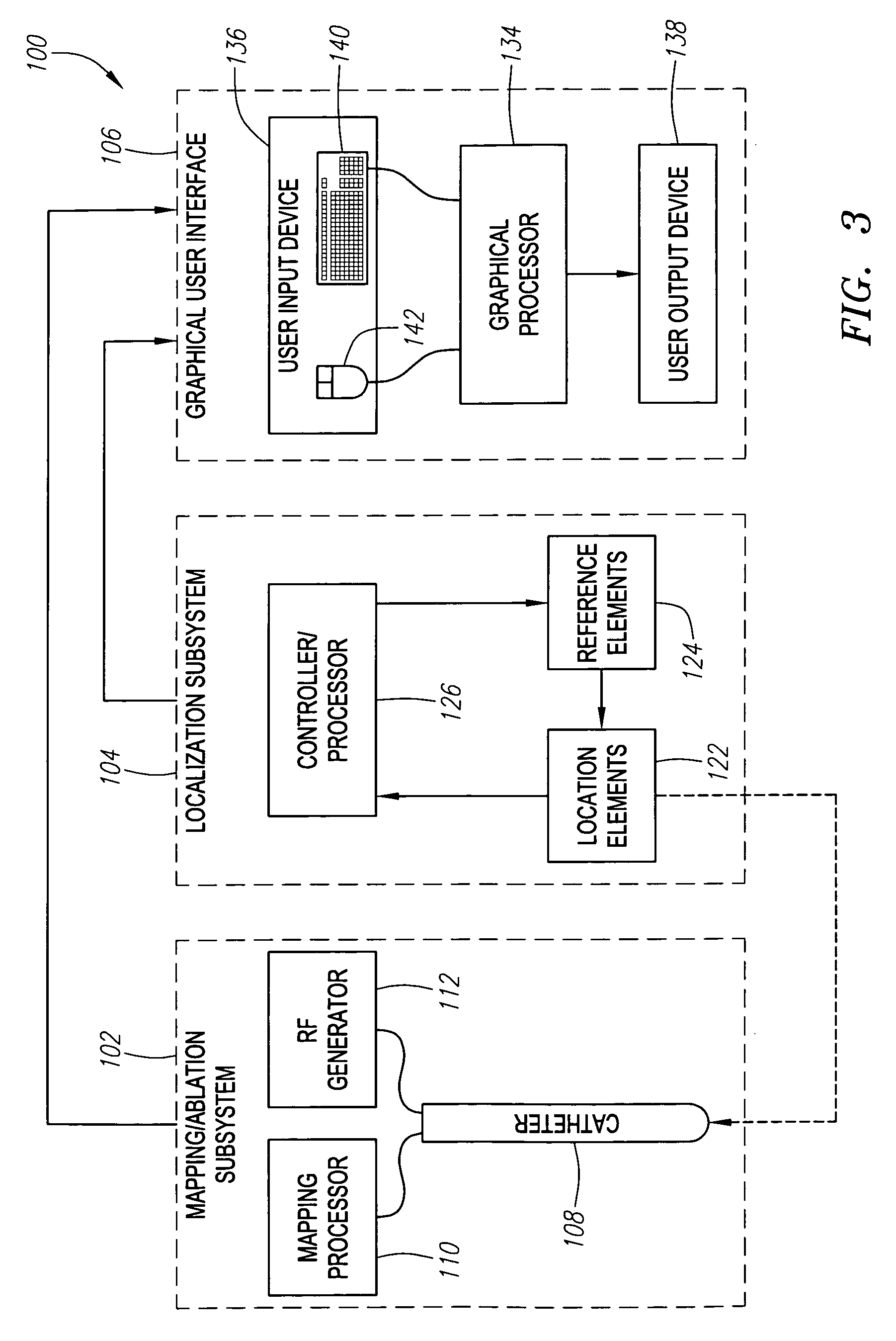
[0024] Referring to FIG. 3, an exemplary catheter navigation system 100 constructed in accordance with the present invention is shown. The navigation system 100 is particularly suited for mapping and treating the heart with catheters. Nevertheless, it should be appreciated that it can be used for treating other internal anatomical structures, e.g., the prostrate, brain, gall bladder, uterus, esophagus and other regions in the body, and can be used to navigate medical devices other than catheters.

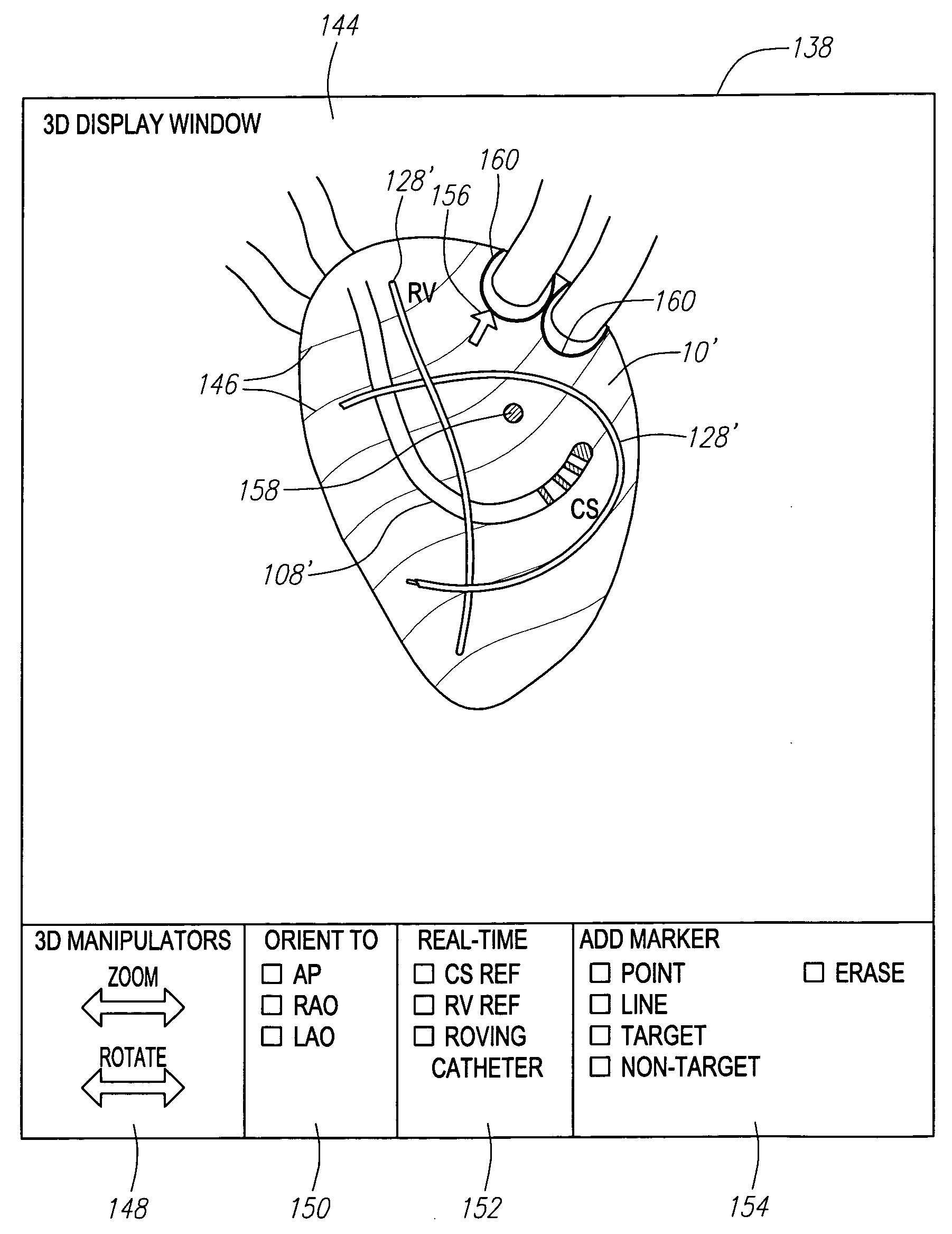
[0025] The navigation system 100 generally comprises (1) a mapping / ablation subsystem 102 for mapping and ablating tissue within the heart; (2) a localization subsystem 104 for registering mapping data and the movement of a probe within a three-dimensional coordinate system; and (3) a graphical user interface 106 configured for generating and displaying graphics of the heart, mapping data, and probe within the three-dimensional coordinate system. The graphical user interface 106 is also con...


PUM


Abstract

The present invention provides systems and method for navigating a medical probe (such as a catheter) relative to an anatomical body (such as a heart). A mark (such as a point or line), representing an anatomical region of interest (such as tissue targeted for treatment or tissue not targeted for treatment) is displayed on a representation of the anatomical body. The positions of the medical probe and the mark are determined within a three-dimensional coordinate system, and the proximity between the medical probe and the mark determined based on these positions. This proximity can then be indicated to a user, e.g., using graphics, text, or audible sounds.

Description

FIELD OF THE INVENTION [0001] The present inventions generally relate to medical probes, and more particularly to systems and methods for navigating medical probes within anatomical organs or other anatomical structures. BACKGROUND OF THE INVENTION [0002] It is often necessary or desirable to determine the location of a medical probe relative to a location of interest within three-dimensional space. In many procedures, such as interventional cardiac electrophysiology therapy, it is important for the physician to know the location of a probe, such as a catheter, (especially, a therapeutic catheter) relative to the patient's internal anatomy. During these procedures, a physician, e.g., steers an electrophysiology mapping catheter through a main vein or artery into the interior region of the heart that is to be treated. The physician then determines the source of the cardiac rhythm disturbance (i.e., the targeted cardiac tissue) either strictly by anatomical considerations or by placin...

Claims


Application Information

Patent Timeline
IPC IPC(8): A61M25/00
CPCA61B5/0422A61B6/12A61B6/503A61B6/5235A61B6/5247A61B6/547A61B8/0833A61B8/0841A61B8/0883A61B8/5238A61B5/287
Inventor MCGEE, DAVID L.WILLIS, N. PARKER
Owner BOSTON SCI SCIMED INC
Features
  • Generate Ideas
  • Intellectual Property
  • Life Sciences
  • Materials
  • Tech Scout
  • Unparalleled Data Quality
  • Higher Quality Content
  • 60% Fewer Hallucinations
Learn More