
Support assembly for loading and securing a tender

a technology for supporting struts and watercraft, which is applied in the direction of vessel safety, vessel transportation, floating buildings, etc., can solve the problems of difficulty in addressing all the different requirements for lifting, loading and securing the tender with ease, and tear out the supporting struts, etc., to achieve easy and fast loading and easy loading

Active Publication Date: 2006-06-08
ANCHOR WELDING
View PDF11 Cites 3 Cited by
  • Summary
  • Abstract
  • Description
  • Claims
  • Application Information

AI Technical Summary

Benefits of technology

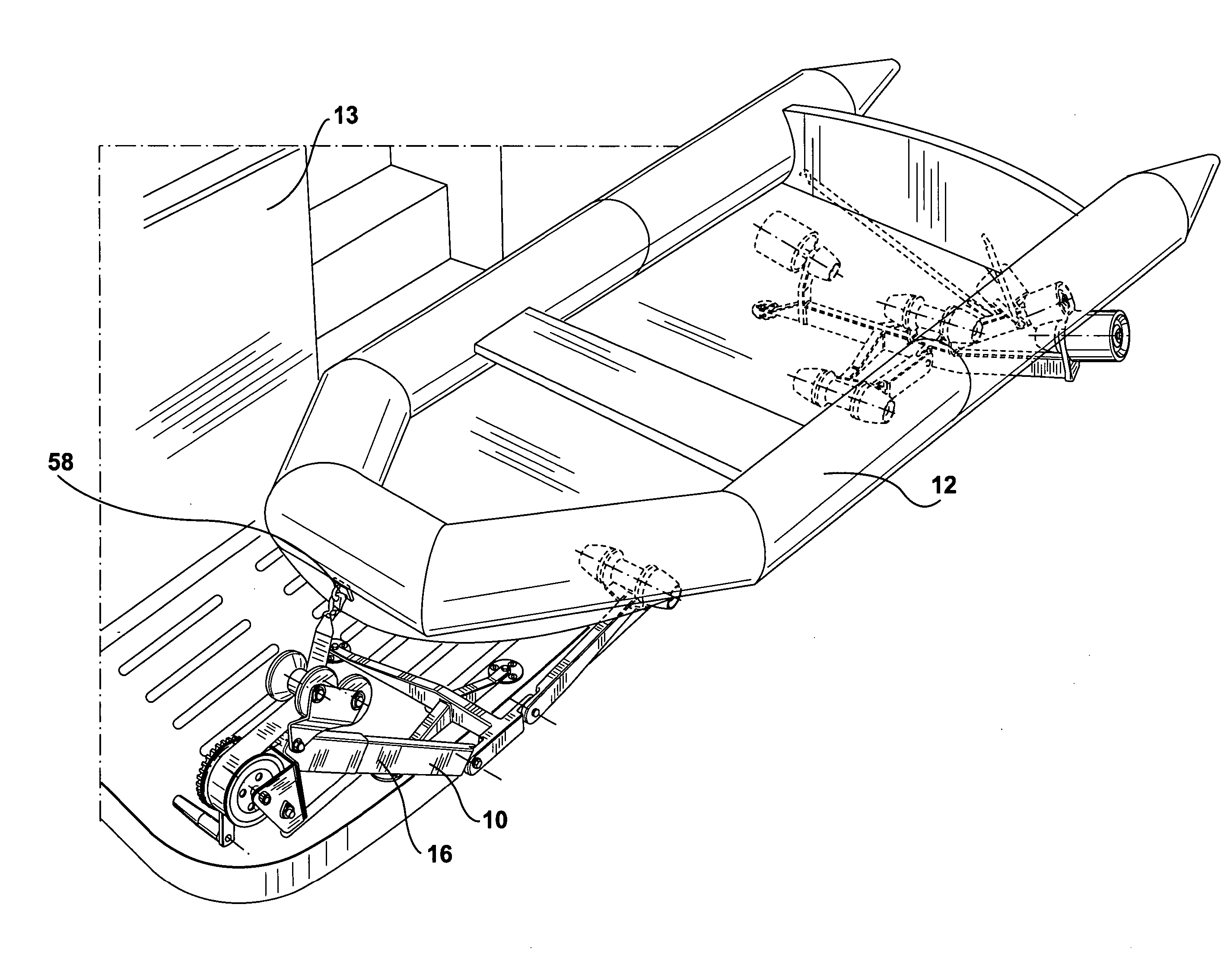
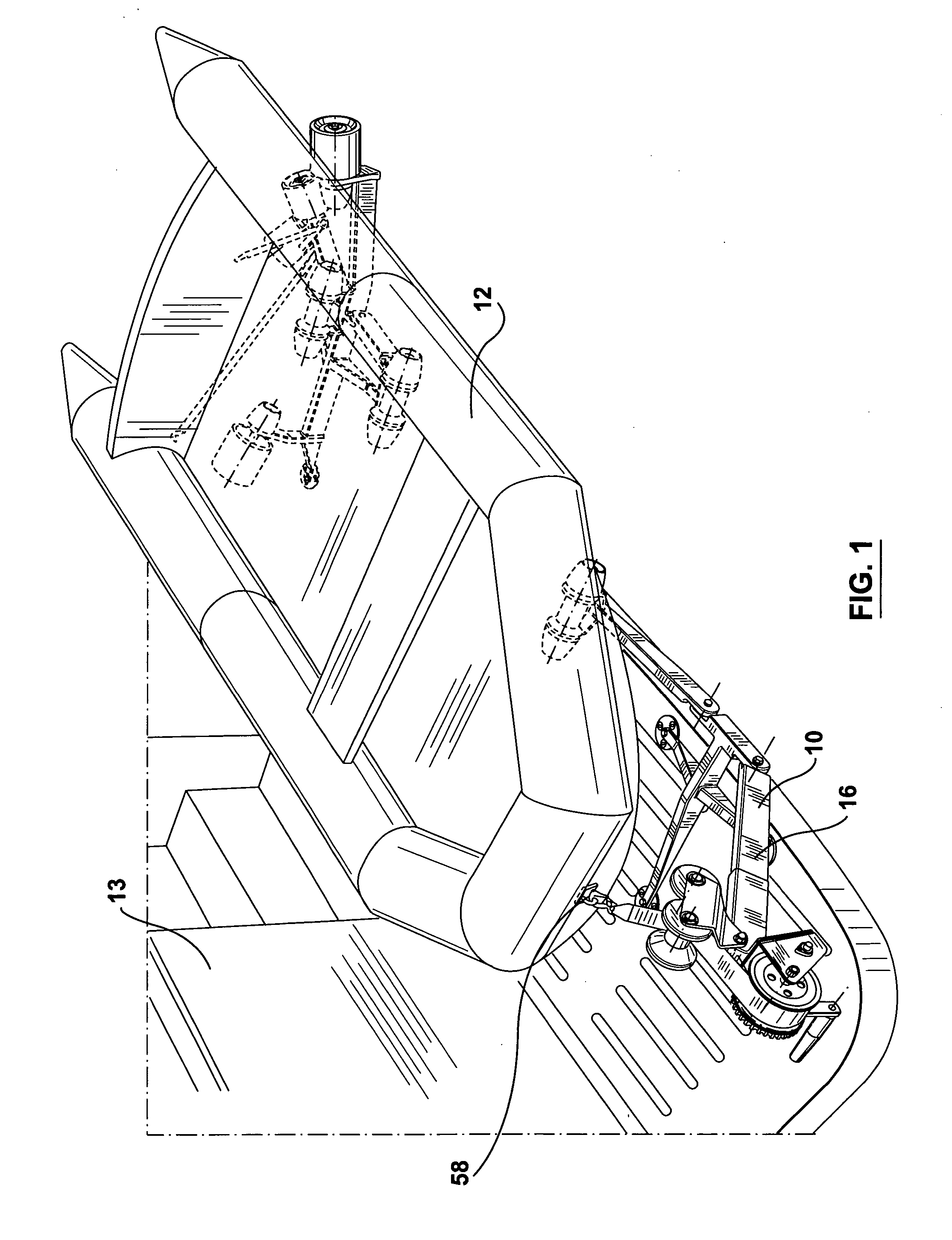
[0008] Both subassemblies may allow for the natural positioning of the tender on the support assembly. The positioning of the tender on the subassemblies does not require the outboard motor, the fuel tank or life jackets to be removed making it easy and faster to load the tender to the watercraft. Furthermore the configuration of the subassemblies may allow for the easy loading with the aid of a winching assembly.

Problems solved by technology

As the tender or dingy can come in a wide a variety of shapes and sizes, it is difficult to address all the different requirements for lifting, loading and securing the tender with ease, namely the weight of the tender or the presence of an outboard motor by way of example only.
Furthermore depending on how the tender is secured to the watercraft, rough waves can actually lift the secured tender and may tear out the supporting struts of traditional platforms on the stern of the watercraft.

Method used


Image

  • Support assembly for loading and securing a tender
  • Support assembly for loading and securing a tender
  • Support assembly for loading and securing a tender

Examples


Embodiment Construction

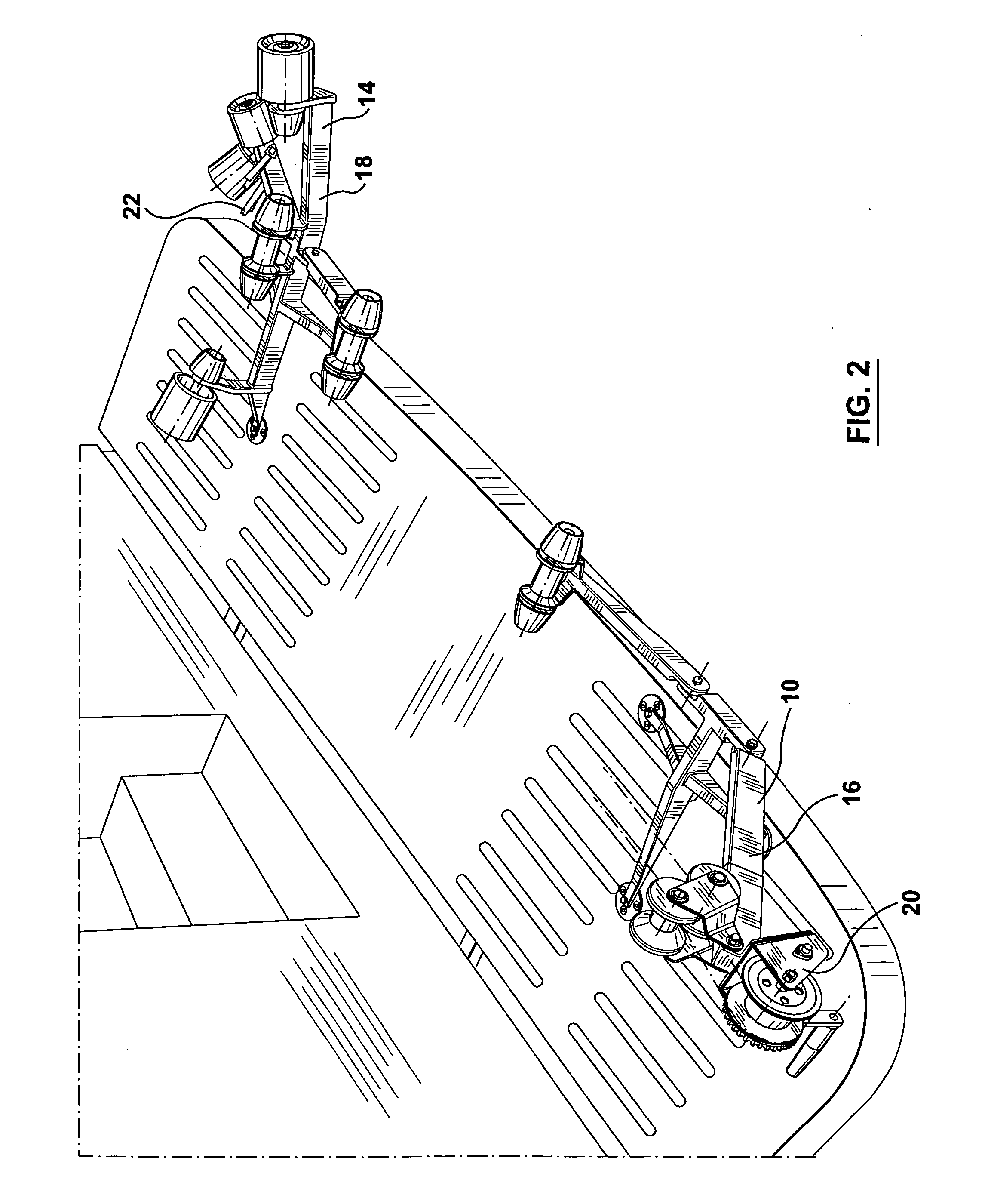
[0022] Referring to FIGS. 1 to 3, there is illustrated in a perspective view, a support assembly 10 for loading and securing a tender 12 to a watercraft 13 in accordance with a preferred embodiment of the present invention. The support assembly 10 for loading and securing a tender 12 includes a roller assembly 14 having a first subassembly 16 and a second subassembly 18. The first assembly 16 may further comprise of a positioning means 20 for positioning the tender 12 on the support assembly 10. The second subassembly 18 may further comprise of a releasable securing means 22 that secures the tender 12 to the support assembly 10.

[0023] Referring to FIGS. 3 and 4a the first assembly 16 may include a series of shafts 24 operatively connected to one another. More specifically a first shaft 26 having a first end 28 and a second end 30, may have mounted to the first end 28 the positioning means 20. A second shaft 32 may have a plurality of attachment zones 38 so that the second end 30 of...


PUM


Abstract

A support assembly for loading and securing a tender including first and second subassemblies. The first assembly includes a winch assembly for positioning the tender on the support assembly and the second subassembly includes a releasable securing device. Both subassemblies include a series of pivotal shafts having rollers which help guide and support the tender into position.

Description

FIELD OF THE INVENTION [0001] This invention relates in general to devices for boats and more particularly to a device for loading and handling a tender for a watercraft. BACKGROUND OF THE INVENTION [0002] Most large watercraft have a tender or dingy that is some how mounted to the watercraft that is used for moving people or various items to and from the watercraft. In general the tender or dingy can come in a variety of forms. They may be inflatable, motorized and in general are light weight. Depending on the weight of the tender they may be manually secured and raised onto the watercraft or they may be secured using some form of powered lifting mechanism. As the tender or dingy can come in a wide a variety of shapes and sizes, it is difficult to address all the different requirements for lifting, loading and securing the tender with ease, namely the weight of the tender or the presence of an outboard motor by way of example only. Furthermore depending on how the tender is secured...

Claims


Application Information

Patent Timeline
IPC IPC(8): B63B21/58B63B23/30B63B23/38B63B23/48B63B23/62
CPCB63B23/30B63B23/48B63B23/62
Inventor ZANDER, RUDY
Owner ANCHOR WELDING
Learn More