RFID label, method for producing the RFID label, device for producing the RFID label, sheet member (tag sheet) used for the RFID label, and cartridge attached to the device for producing the RFID label

a technology of rfid label and label, applied in the direction of paper/cardboard articles, instruments, paper/cardboard containers, etc., can solve the problems of image not being formed in a normal manner, heat or pressure applied when the image is formed, and damage to the rfid antenna conductor and other elements included in the rfid label

Active Publication Date: 2006-06-08
BROTHER KOGYO KK
View PDF17 Cites 72 Cited by
  • Summary
  • Abstract
  • Description
  • Claims
  • Application Information

AI Technical Summary

Benefits of technology

[0024] The invention in claim 2 provides a RFID label wherein being produced according to the method of claim 1. In this RFID label, an image is formed on the surface to be joined to the second label base material of the first label base material, and the image-formed surface is covered with the second label base material. According to the RFID label according to claim 2, since no element comes into contact with the image-formed surface directly from outside, the image formed thereon can be prevented, for example, from being worn out, and the image can be kept in an excellent state.
[0073] The invention in claim 60 provides the tag tape roll of claim 52, wherein the gluing adhesive layer or the fixing adhesive layer or the intermediate adhesive layer is formed to become stronger in adhesive force than the other adhesive layers. As a result, when a produced label receives a force in a direction in which the label is peeled off, the gluing adhesive layer or the fixing adhesive layer or the intermediate adhesive layer spontaneously separates and breaks into pieces, and hence the remaining parts other than these, in particular, the RFID circuit element, can be prevented from being destroyed. That is, it becomes possible to realize a security tape capable of storing internal information.

Problems solved by technology

In other words, if an image is formed on the RFID label after joining the first label base material which is transparent and the second label base material including at least one (hereinafter, referred to as the “IC chip or the like”) of the RFID antenna conductor and the IC chip together, there is a fear that the heat or pressure applied when the image is formed will damage the RFID antenna conductor and other elements included in the RFID label, and there is a fear that, for example, a concave and a convex generated by the IC chip or the like will appear on the surface of the RFID label, and hence the image cannot be formed in a normal manner.

Method used


Image

  • RFID label, method for producing the RFID label, device for producing the RFID label, sheet member (tag sheet) used for the RFID label, and cartridge attached to the device for producing the RFID label
  • RFID label, method for producing the RFID label, device for producing the RFID label, sheet member (tag sheet) used for the RFID label, and cartridge attached to the device for producing the RFID label
  • RFID label, method for producing the RFID label, device for producing the RFID label, sheet member (tag sheet) used for the RFID label, and cartridge attached to the device for producing the RFID label

Examples


first embodiment

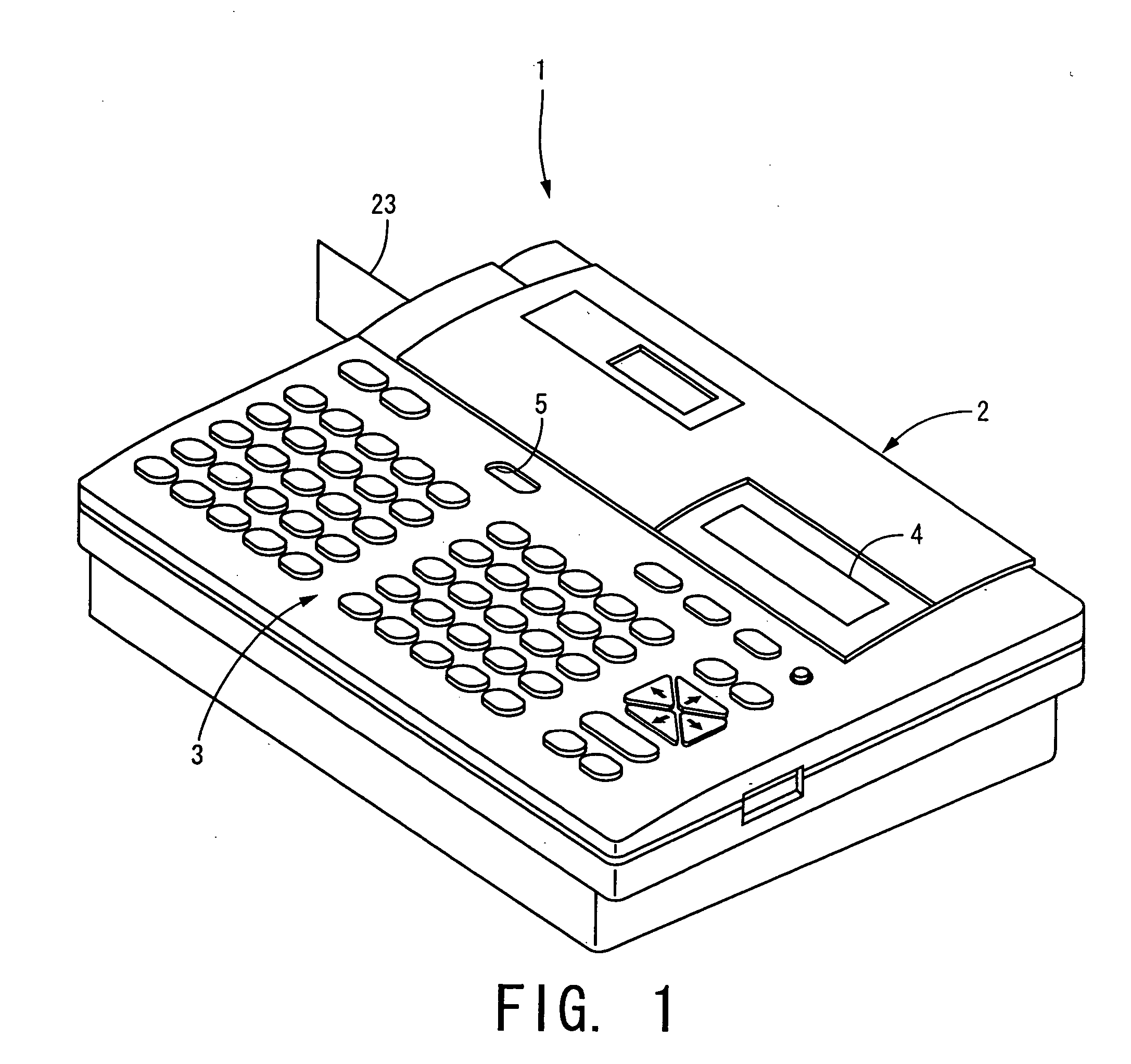
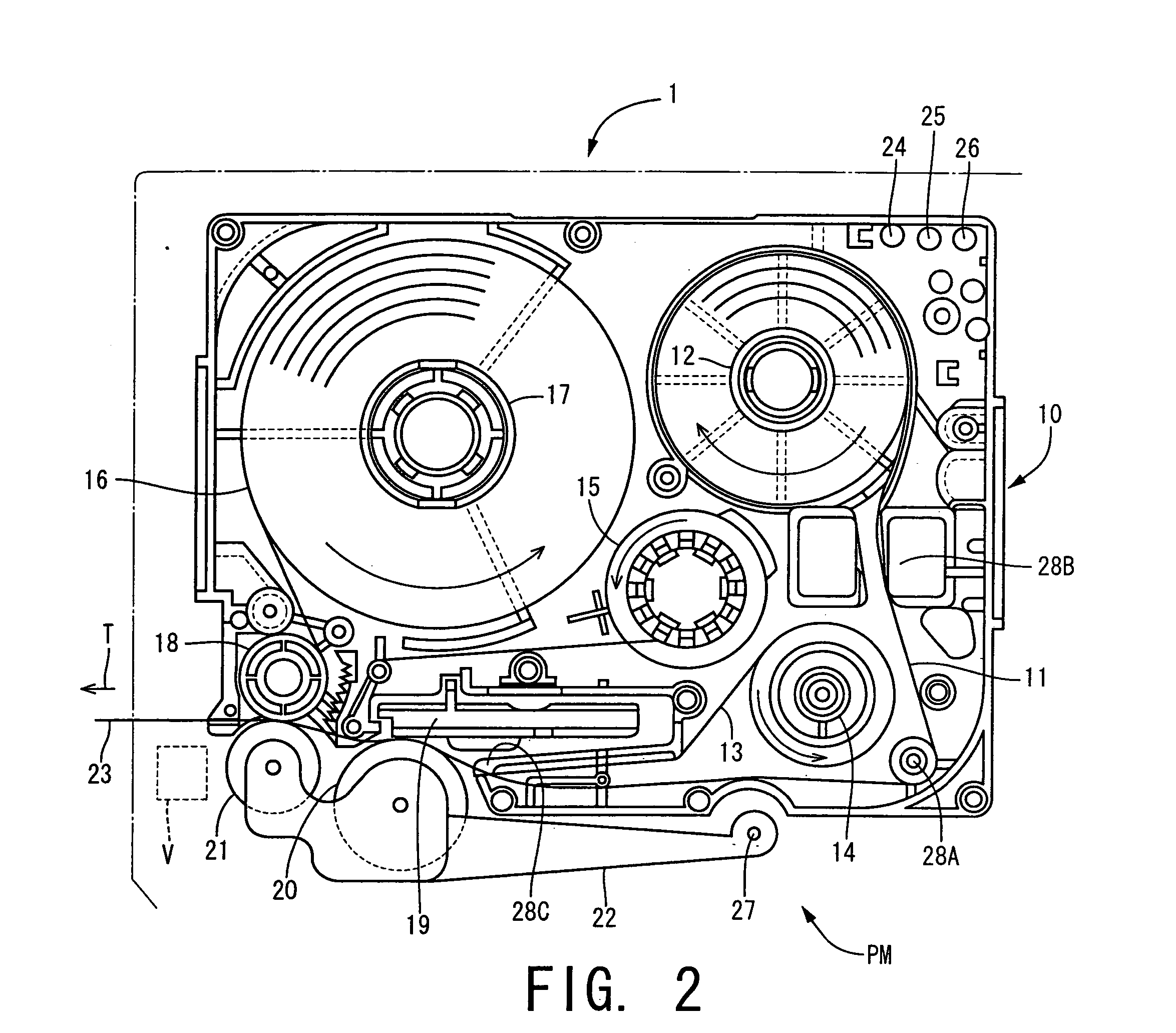
[0118]FIG. 1 is a perspective view showing the whole of a RFID label producing device 1 for producing a RFID label 70 called a RFID tag, for example.

[0119] In FIG. 1, a keyboard 3 is disposed at the front part of the RFID label producing device 1. A thermal printing mechanism PM (see FIG. 2) corresponding to an image forming means of the present invention is disposed inside the RFID label producing device 1 and behind the keyboard 3. A cover case 2 that can be opened and closed to exchange a cartridge 10 shown in FIG. 2 is disposed behind the keyboard 3. The cover case 2 has a display 4, such as a liquid crystal display (LCD), on which characters or symbols input by the keyboard 3 are displayed. An operating knob 5 that is operated to open the cover case 2 is disposed between the cover case 2 and the keyboard 3.

[0120] The keyboard 3 has character keys used to input alphabetical letters, numerals, and marks, space keys, end-of-line keys, cursor moving keys used to move a cursor fro...

second embodiment

[0163] Next, another embodiment of the present invention will be described. In the following description, the same reference numerals as in the foregoing embodiment are given to the same element, and a description of the same element are omitted.

[0164]FIG. 7A is a sectional side view of a RFID label 70 using a laminate tape 11 according to another embodiment. The RFID label 70 of FIG. 7A is different from the aforementioned RFID label 70 (see FIG. 4A to FIG. 5B) only in the laminate tape 11 used to produce the RFID label 70.

[0165] The laminate tape 11 of FIG. 7A according to this embodiment is not a mere transparent film. This laminate tape 11 has a thermosensitive layer 11A that includes a color-producing reagent prepared so that a heated part can be colored by local heating in its surface to be joined to the band-shaped sheet member 16 and that is partially colored into a preset color, such as black or blue.

[0166] The thus structured laminate tape 11 is drawn from the cartridge...

third embodiment

[0196]FIG. 11 shows an example in which square or rectangular sheet members 16 or RFID labels 70 are contained in a box P, which is a wrapper, shown by the alternate long and short dash line, for example, to sell the band-shaped sheet members 16 as a single item. In this example, the band-shaped sheet members 16 are conveyed while each tape is peeled off so as to sequentially produce the RFID labels 70. Even in this example, an image printed on the RFID label 70 can be kept in an excellent state without damaging the IC chip 64 and the other elements included in the RFID label 70.

[0197] Since the IC chips 64 are disposed so as not to coincide with each other in the plane direction between the sheet members 16 or the RFID labels 70 adjoining in the thickness direction, the box P can be made smaller, or, if the size of the box P is fixed, more sheet members 16 or more RFID labels 70 can be contained therein.


PUM

PropertyMeasurementUnit
widthsaaaaaaaaaa
widthsaaaaaaaaaa
widthsaaaaaaaaaa

Abstract

A method for producing a RFID label comprises conveying a first label base material which is transparent from a first holding portion holding the first label base material, forming an image on a surface of the first label base material, conveying a second label base material including at least one of a RFID antenna conductor and an IC chip from a second holding portion holding the second label base material and joining the second label base material and the first label base material on which an image has been formed together, wherein, when an image is formed on the first label base material, the image is formed on a surface of the first label base material, the surface being joined to the second label base material.

Description

BACKGROUND OF THE INVENTION [0001] This invention relates to a RFID (Radio Frequency Identification) label in which information data wirelessly sent from outside can be stored or from which information data can be wirelessly read toward the outside, a method for producing the RFID label, a device for producing the RFID label, a sheet member used for the RFID label, and a cartridge that can be mounted on the producing device. [0002] Conventionally, a data capturing system for capturing data about articles of commerce while using RFID labels, in each of which an IC chip or the like is embedded, is known as an example of a system in which data stored in such a RFID label is wirelessly exchanged (see Patent Document 1, for example). [0003] For example, an electromagnetic induction method is applied to the RFID label used in the data capturing system. According to this method, when the RFID label attached to an article enters a magnetic field, an electromotive force is generated in a res...

Claims


Application Information

Patent Timeline
Patent Type & Authority Applications(United States)
IPC IPC(8): B31B1/60B32B29/02G08B13/14H01Q17/00H05K3/00
CPCG06K19/077G06K19/07718G06K19/07749H01Q1/22H01Q1/2225Y10T29/49124B31D1/027B31D1/028Y10T29/49018Y10T156/10B31D1/021
Inventor OHASHI, TSUYOSHITAKI, KAZUNARIYASUI, KUNIHIRONAGAI, TAKUYATAKAHASHI, TOSHIONAKAMURA, YASUNORI
Owner BROTHER KOGYO KK
Why Eureka
Try Eureka