Aiming pattern for imaging-based bar code readers

a bar code reader and pattern technology, applied in the field of aiming patterns, can solve the problem that the user of the device cannot be expected to manually focus the imaging system, and achieve the effects of increasing intensity, reducing the amount of time, and increasing thickness

Active Publication Date: 2006-06-08
SYMBOL TECH LLC
View PDF5 Cites 43 Cited by
  • Summary
  • Abstract
  • Description
  • Claims
  • Application Information

AI Technical Summary

Benefits of technology

[0009] An aiming pattern includes a relatively long and thick horizontal line and a perpendicular relatively short and thin vertical line that form a crosshair pattern. The combination of the thick horizontal line and the thin vertical line yields an aiming pattern that can be effectively used for ranging purposes while at the same time providing sufficient illumination for decoding 1-D barcodes.
[0011] It may be advantageous that the horizontal line has a relatively large thickness sufficient to cover speckle noise that would be collected by the segment of the two-dimensional array and / or if the two dimensional array is adapted such that a segment of the two-dimensional array corresponding to the swath illuminated by the aiming pattern can be read out in a shorter amount of time than is required to read out the entire two-dimensional array. The aiming pattern generator may also adjust an intensity of the aiming pattern based on the determined distance between the imaging system and the target object such that, for example, the aiming pattern generator increases the intensity of the aiming pattern as the determined distance increases.

Problems solved by technology

Whether the imaging system is housed in a handheld, portable bar code reader or a permanently mounted reader, the user of the device cannot be expected to manually focus the imaging system by moving the lens, thus, there is a need for an automatic focusing system or auto focus system for an imaging system.

Method used


Image

  • Aiming pattern for imaging-based bar code readers
  • Aiming pattern for imaging-based bar code readers
  • Aiming pattern for imaging-based bar code readers

Examples


Embodiment Construction

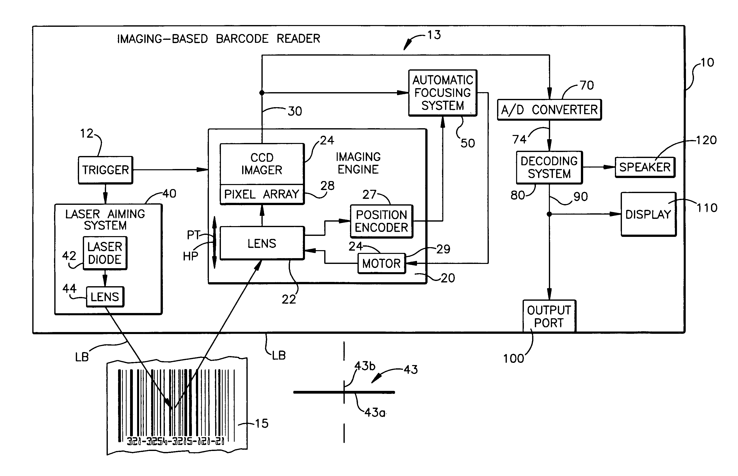
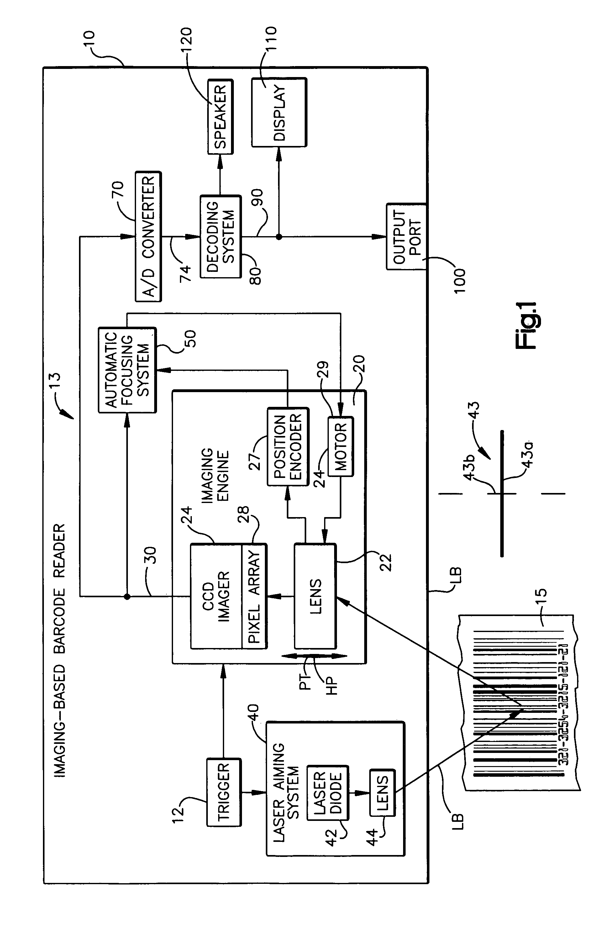
[0019] An imaging-based bar code reader is shown schematically at 10 in FIG. 1. The bar code reader 10, in addition to imaging and decoding both 1D and 2D bar codes and postal codes, is also capable of capturing images and signatures. In one preferred embodiment of the present invention, the bar code reader 10 is a hand held portable reader that can be carried and used by a user walking or riding through a store, warehouse or plant for reading bar codes for stocking and inventory control purposes.

[0020] However, it should be recognized that an aiming pattern of the present invention, to be explained below, may be advantageously used in connection with any type of imaging-based automatic identification system including, but not limited to, bar code readers, signature imaging acquisition and identification systems, optical character recognition systems, fingerprint identification systems and the like. It is the intent of the present invention to encompass all such imaging-based autom...


PUM


Abstract

An aiming pattern is used with an automatic focusing system for an imaging-based bar code reader. The combination of the thick horizontal line and the thin vertical line yields an aiming pattern that can be effectively used for ranging purposes while at the same time providing sufficient illumination for decoding 1-D barcodes.

Description

CROSS REFERENCE TO RELATED APPLICATIONS [0001] This application is a continuation-in-part of U.S. patent application Ser. No. 10 / 903,792 filed on Jul. 30, 2004, which is assigned to the assignee of the present invention, and incorporated herein by reference in its entirety.FIELD OF THE INVENTION [0002] The present invention relates to an aiming pattern that can be used with an automatic focusing system for an imaging-based bar code reader. BACKGROUND OF THE INVENTION [0003] Various electro-optical systems have been developed for reading optical indicia, such as bar codes. A bar code is a coded pattern of graphical indicia comprised of a matrix or series of bars and spaces of varying widths, the bars and spaces having differing light reflecting characteristics. Systems that read and decode bar codes employing CCD or CMOS-based imaging systems are typically referred to as imaging-based bar code readers or bar code scanners. [0004] Imaging systems include CCD arrays, CMOS arrays, or ot...

Claims


Application Information

Patent Timeline
Patent Type & Authority Applications(United States)
IPC IPC(8): G06K7/10
CPCG02B7/08G06K7/10811G06K2207/1011G06K7/10
Inventor JOSEPH, EUGENECARLSON, BRAD
Owner SYMBOL TECH LLC
Why Eureka
Try Eureka