
Leakage current interrupter

a leakage current and interrupter technology, applied in the field can solve the problems of increasing manufacturing cost and product size of leakage current interrupters, and achieve the effect of decreasing manufacturing cost and product siz

Inactive Publication Date: 2006-06-08
DAESUNG ELECTRIC CO LTD
View PDF2 Cites 24 Cited by
  • Summary
  • Abstract
  • Description
  • Claims
  • Application Information

AI Technical Summary

Benefits of technology

[0008] In order to solve the foregoing and / or other problems, it is an aspect of the present invention to provide a leakage current interrupter capable of remarkably decreasing manufacturing cost and product size by detecting a leakage current through a resistor.

Problems solved by technology

However, since the conventional leakage current interrupter should use a separate transformer to detect the leakage current, and perform a leakage current interrupting function therethrough, the manufacturing cost and product size of the leakage current interrupter increase.

Method used


Image

  • Leakage current interrupter
  • Leakage current interrupter
  • Leakage current interrupter

Examples


Embodiment Construction

[0015] Reference will now be made in detail to the embodiments of the present invention, examples of which are illustrated in the accompanying drawings, wherein like reference numerals refer to the like elements throughout. The embodiments are described below in order to explain the present invention by referring to the figures.

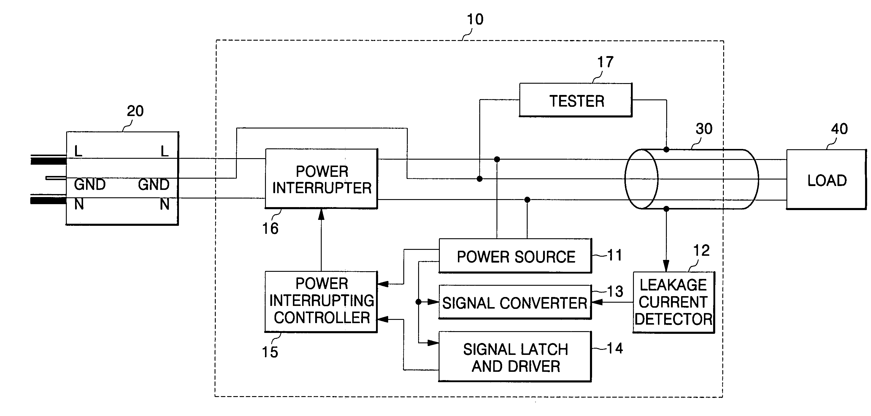
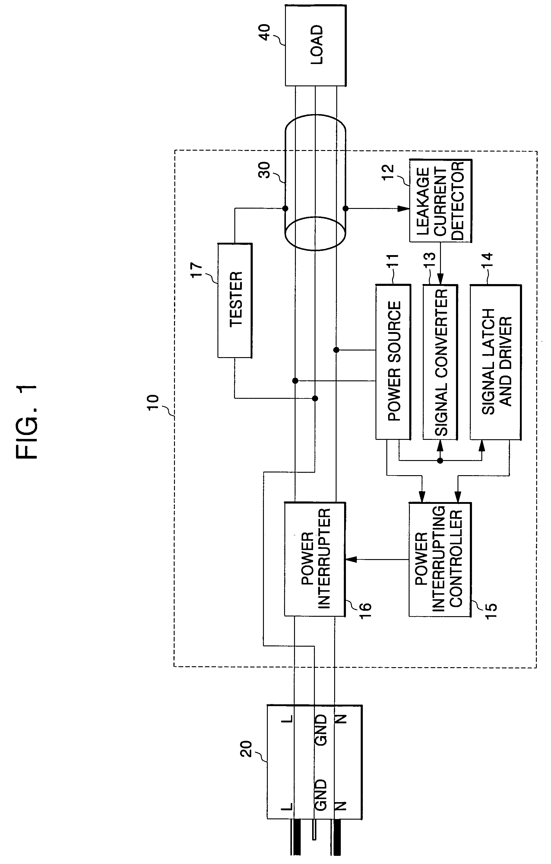
[0016]FIG. 1 is a block diagram of the interior of a leakage current interrupter in accordance with the present invention.

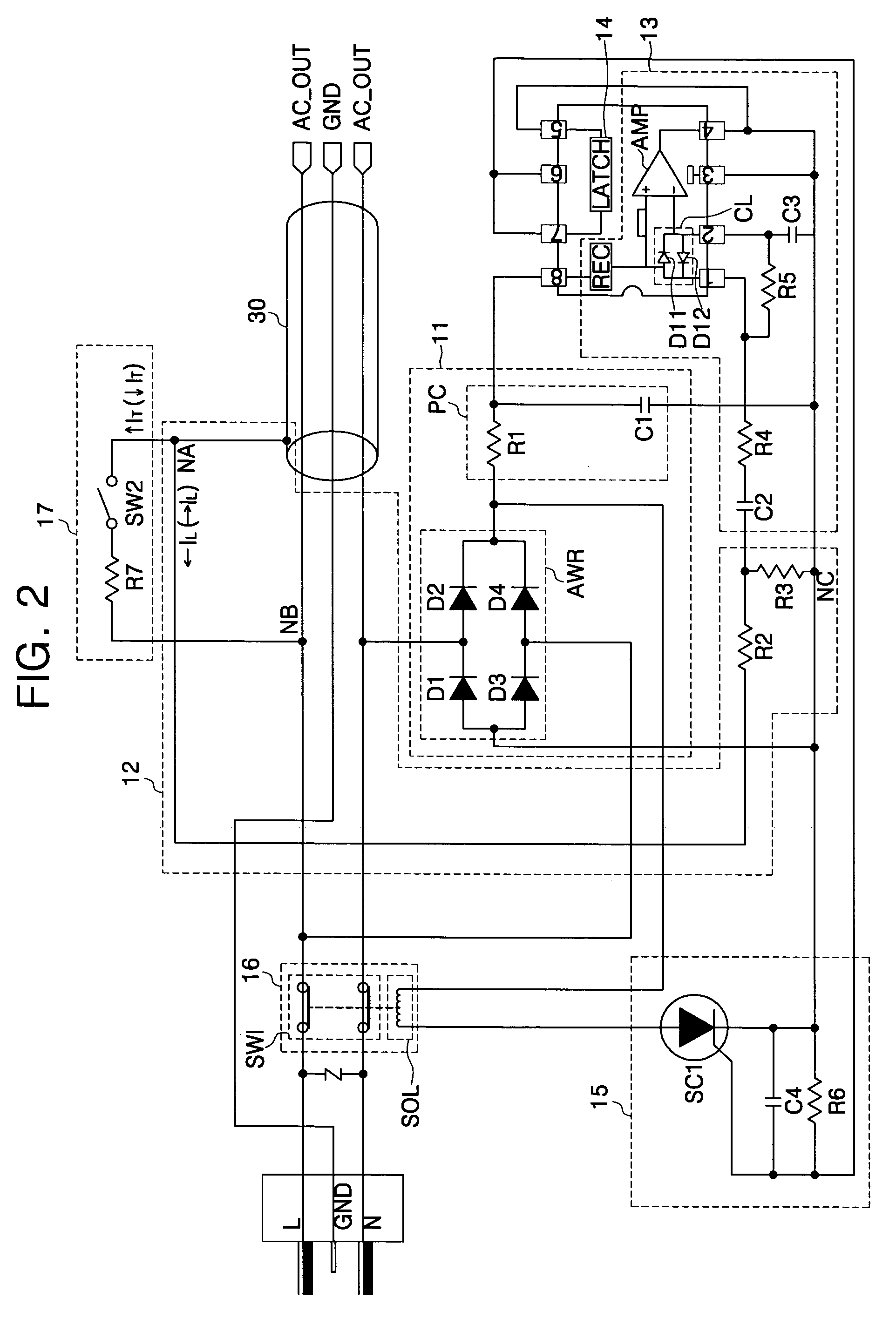
[0017] As shown in FIG. 1, the leakage current interrupter 10 of the present invention is connected to an electric outlet 20 and a power cable 30, and includes a power source 11, a leakage current detector 12, a signal converter 13, a signal latch and driver, a power interrupting controller 15, a power interrupter 16, and a tester 17.

[0018] The power source 11 is connected to a power line L and a neutral line N to receive an alternating current (AC) power source, to thereby generate operating power for interrupting the connection of the...


PUM


Abstract

A leakage current interrupter is provided. The leakage current interrupter includes: a leakage current detector having resistors connected to the external metal cover of the power cable, and generating a voltage corresponding to a leakage current through the resistors when the leakage current flows through the external metal cover of the power cable; a power source connected to the power line and the neutral line to generate DC power when AC power is applied through the power line and the neutral line; a power interrupter opening the power line and the neutral line when the DC power is applied; and a controller applying the DC power to the power interrupter when the leakage current detector generates a voltage. Therefore, it is possible to reduce manufacturing cost, and to provide a self-test function to the leakage current interrupter to increase the operation reliability of the leakage current interrupter. Therefore, it is possible to reduce manufacturing cost, and to provide a self-test function to the leakage current interrupter to increase operation reliability of the leakage current interrupter.

Description

CROSS-REFERENCE TO RELATED APPLICATION [0001] This application claims the benefit of Korean Patent Application No. 2004-101423, filed Dec. 3, 2004, the disclosure of which is hereby incorporated herein by reference in its entirety. BACKGROUND OF THE INVENTION [0002] 1. Field of the Invention [0003] The present invention relates to an electric power system and, more particularly, to a leakage current interrupter capable of detecting and interrupting a leakage current when current leaks from a power cable. [0004] 2. Description of the Related Art [0005] A leakage current interrupter, which is used in an electric power system, functions to prevent an accident from occurring by detecting a leakage current through an appropriate circuit, and interrupting a power line, when current leaks from an electric power system. [0006] A conventional leakage current interrupter includes a transformer connected to an external metal cover of a power cable in order to detect a leakage current, an elect...

Claims


Application Information

Patent Timeline
Patent Type & Authority Applications(United States)
IPC IPC(8): H02H3/00
CPCH02H3/335H02H3/08
Inventor LEE, WON-HO
Owner DAESUNG ELECTRIC CO LTD
Learn More