
Method of estimating fading coefficients of channels and of receiving symbols and related single or multi-antenna receiver and transmitter

a channel and receiver technology, applied in the field of digital signal transmission, can solve the problems of delayed estimation of fading coefficients, slow system of estimation, and complex hardware of known receivers for estimating channel characteristics

Active Publication Date: 2006-06-08
STMICROELECTRONICS SRL
View PDF3 Cites 52 Cited by
  • Summary
  • Abstract
  • Description
  • Claims
  • Application Information

AI Technical Summary

Benefits of technology

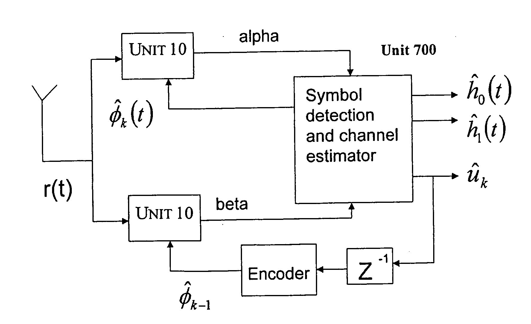
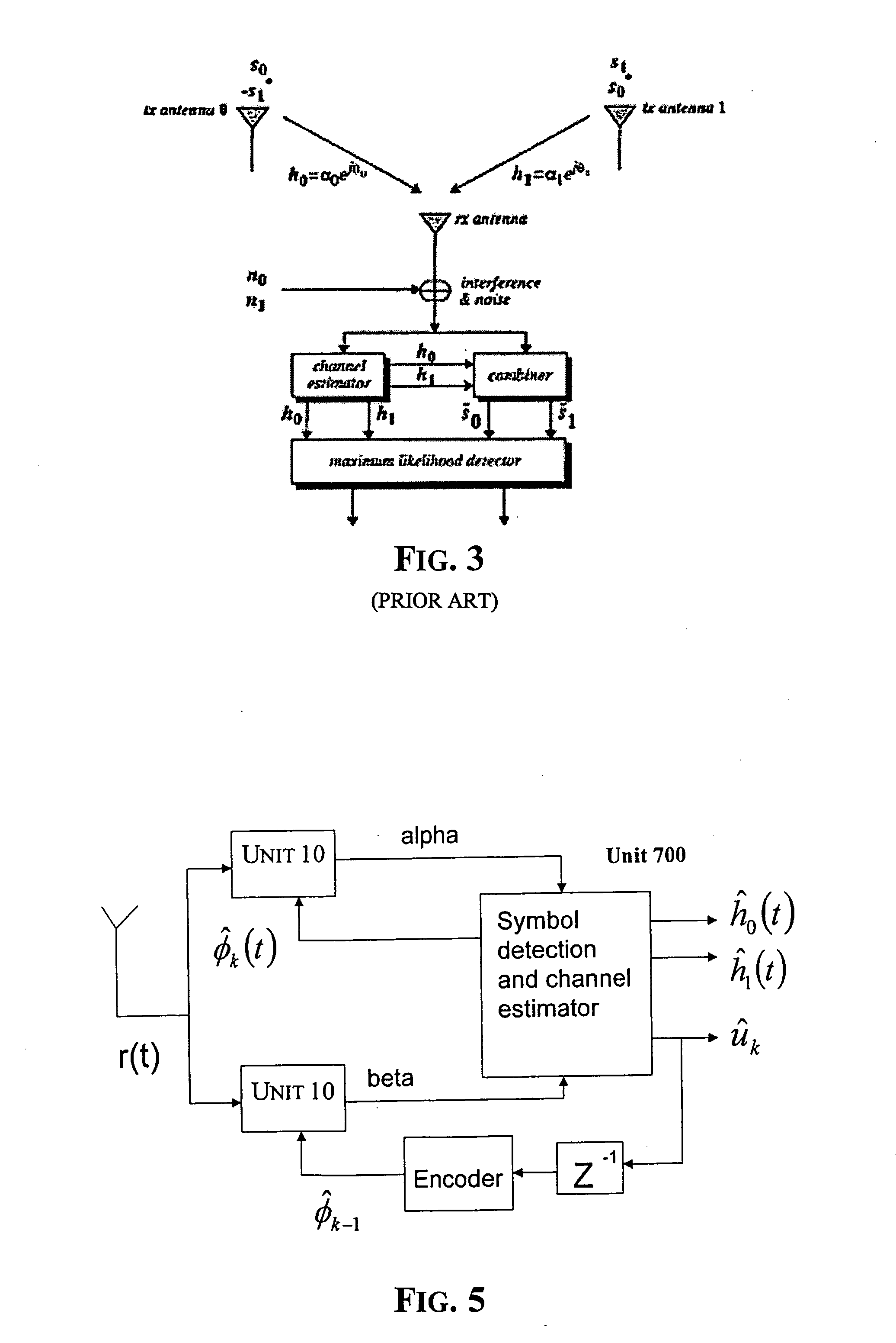
[0020] According to this invention, the fading coefficients are estimated by using estimations of the transmitted symbols obtained in advance with any technique, thus obtaining DC components of the received signal by coherent demodulation locked to the phases of the transmitted AM-PSK signals, and processing these DC components. The method of this invention may be implemented without requiring the choice of a stochastic distribution model of the channel fading, thus it remains efficient even when the channel characteristics vary significantly. Moreover, it works correctly even if the received stream is disturbed by inter-symbolic interference (ISI) and / or by multi-path fading.

Problems solved by technology

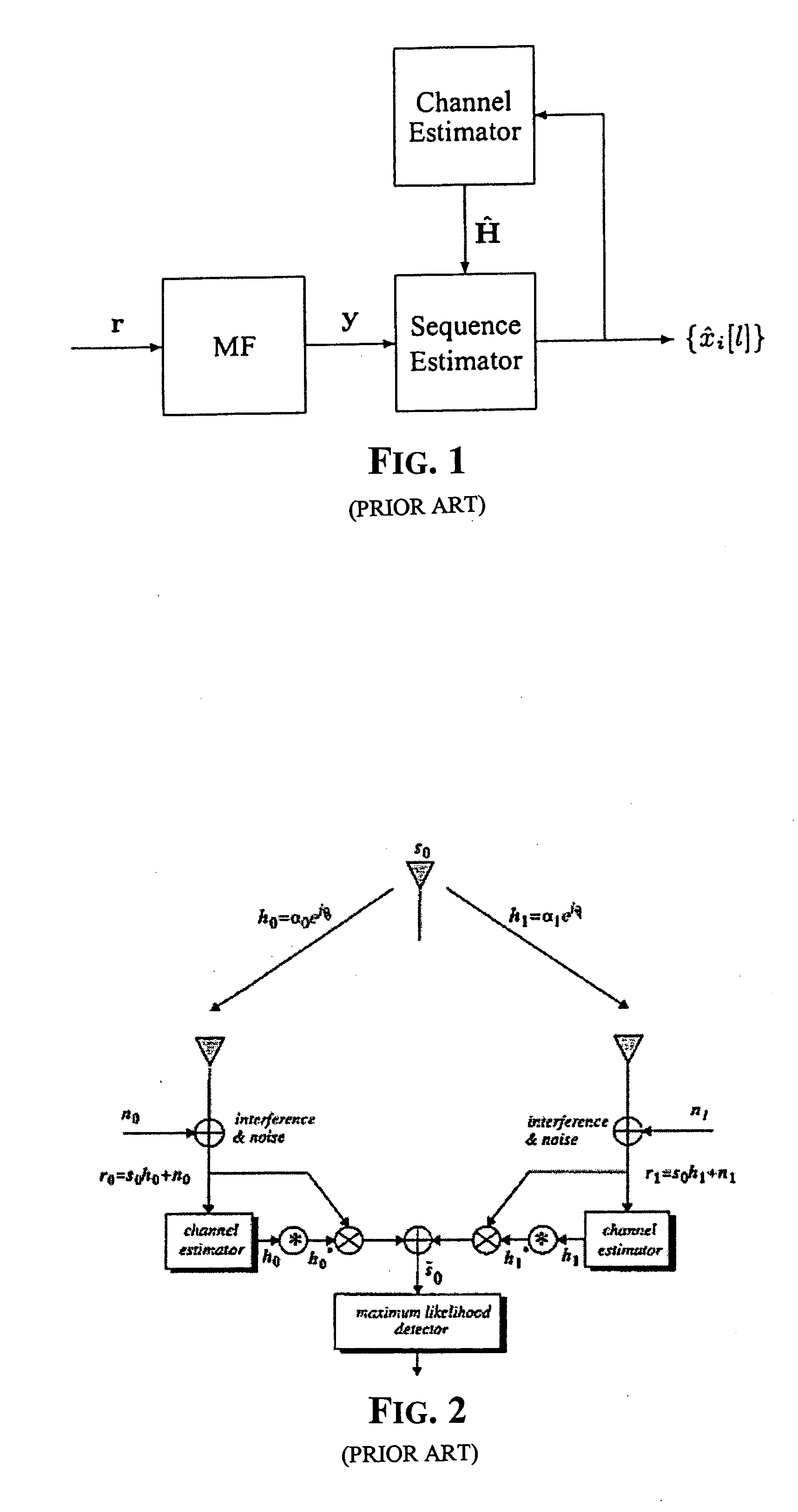
Known receivers have a quite complex hardware for estimating the channel characteristics.
Kalman filters have drawbacks because they introduce a significant delay in the estimation of the fading coefficients, thus these receivers require a faster system of estimation of the channel characteristics.
To correctly receive the transmitted signals, it is not possible to ignore the different fading coefficients of the channels in use, if satisfactory performances are to be obtained.
If the transmission channel presents characteristics different from the ideal characteristics of the chosen stochastic distribution, the bit-error rate of the receiver could be not satisfactory.

Method used


Image

  • Method of estimating fading coefficients of channels and of receiving symbols and related single or multi-antenna receiver and transmitter
  • Method of estimating fading coefficients of channels and of receiving symbols and related single or multi-antenna receiver and transmitter
  • Method of estimating fading coefficients of channels and of receiving symbols and related single or multi-antenna receiver and transmitter

Examples


Embodiment Construction

[0042] The method of this invention is applicable with Amplitude Modulation / Phase Shift Keyed (AM-PSK) modulated signals. The source symbols uk to be transmitted may be +1 or −1, or they may be chosen in a more numerous set. For ease of understanding, consider the case in which

uk∈{−1,+1}  (1)

In the ensuing description it will be shown how to generalize the invention to the case in which the symbols to be transmitted are identified by two or more bits.

[0043] A generic AM-PSK modulated signal is described by the following equation

s(t)=uk·cos(2πf0t+φk)   (2)

The symbol uk to be transmitted is preferably encoded by a “convolutional encoder”, for instance of the kind disclosed in the book “Digital Communications” by Proakis, third edition. Depending on the symbol uk, a code word ck is generated, to which a phase φk is associated according to the known techniques in PSK transmissions. If no more than four different symbols are used, the phase φk is determined according to the follow...


PUM


Abstract

The method is for estimating the fading coefficients of a plurality of transmission channels on which signals to be sent, generated as a function of a sequence of symbols, are transmitted according to a particular modulation, e.g. AM-PSK modulation. The fading coefficients are estimated by using estimations of the transmitted symbols obtained in advance, thus obtaining DC components of the received signal by coherent demodulation locked to the phases of the transmitted AM-PSK signals, and processing these DC components. The method may not require the choice of a stochastic distribution model of the channel fading, thus it remains efficient even when the channel characteristics vary significantly. Moreover, the method works correctly even if the received stream is disturbed by inter-symbolic interference (ISI) and / or by multi-path fading.

Description

FIELD OF THE INVENTION [0001] The present invention relates in general to the transmission of digital signals and more particularly to methods for estimating fading coefficients of channels for transmitting and receiving symbols and to related architectures of transmitters and receivers with a single antenna or multi-antennas. BACKGROUND OF THE INVENTION [0002] Estimating characteristics of a transmission channel is a particularly important task in the field of wireless communications, for producing receivers of digital signals characterized by a small probability of incorrect recognition of transmitted symbols. Typically, in wireless communications the transmitted signals fade according to a time-variable fading coefficient that must be estimated for correctly recognizing transmitted symbols. For this reason receivers that use the so-called “channel estimators” have been produced. [0003] According to a known technique, certain channel estimator algorithms contemplate the step of se...

Claims


Application Information

Patent Timeline
IPC IPC(8): H04L27/22H03D1/04H04L27/06
CPCH04L25/0224H04L25/061H04L27/32H04L27/3818
Inventor VISALLI, GIUSEPPEAVELLONE, GIUSEPPE
Owner STMICROELECTRONICS SRL
Learn More