Vacuum packaging bags equipped with deflating device and deflating cylinders for use thereof

a vacuum packaging and cylinder technology, applied in the field of vacuum packaging, can solve the problems of reducing the use of vacuum packaging in households, reducing the use of vacuum packaging, and burdening the carrying of vacuum pumps, etc., and achieves the effects of convenient production, convenient use, and simple structur

Inactive Publication Date: 2006-06-08
HAN NGAI
View PDF5 Cites 37 Cited by
  • Summary
  • Abstract
  • Description
  • Claims
  • Application Information

AI Technical Summary

Benefits of technology

[0007] 2) The vacuum packaging bag has a simple structure, it is easy to produce, and convenient to use. If desired, it can be reused.
[0008] 3) The experimental results h

Problems solved by technology

One problem the current technology has is that the vacuum pump is too burdensome to carry around.
Also, vacuum pumps are expensive, which dep

Method used


Image

  • Vacuum packaging bags equipped with deflating device and deflating cylinders for use thereof
  • Vacuum packaging bags equipped with deflating device and deflating cylinders for use thereof
  • Vacuum packaging bags equipped with deflating device and deflating cylinders for use thereof

Examples


example 1

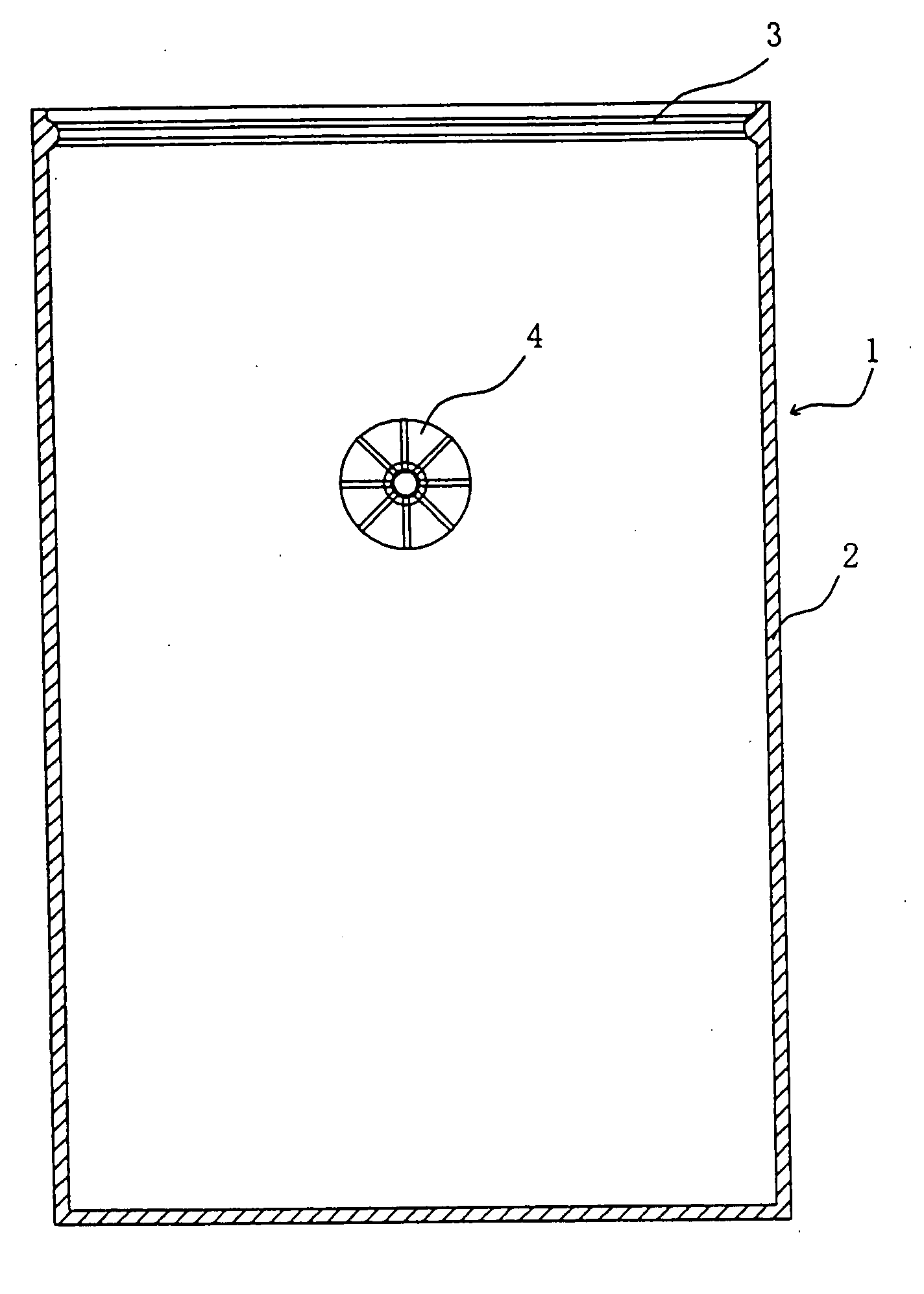
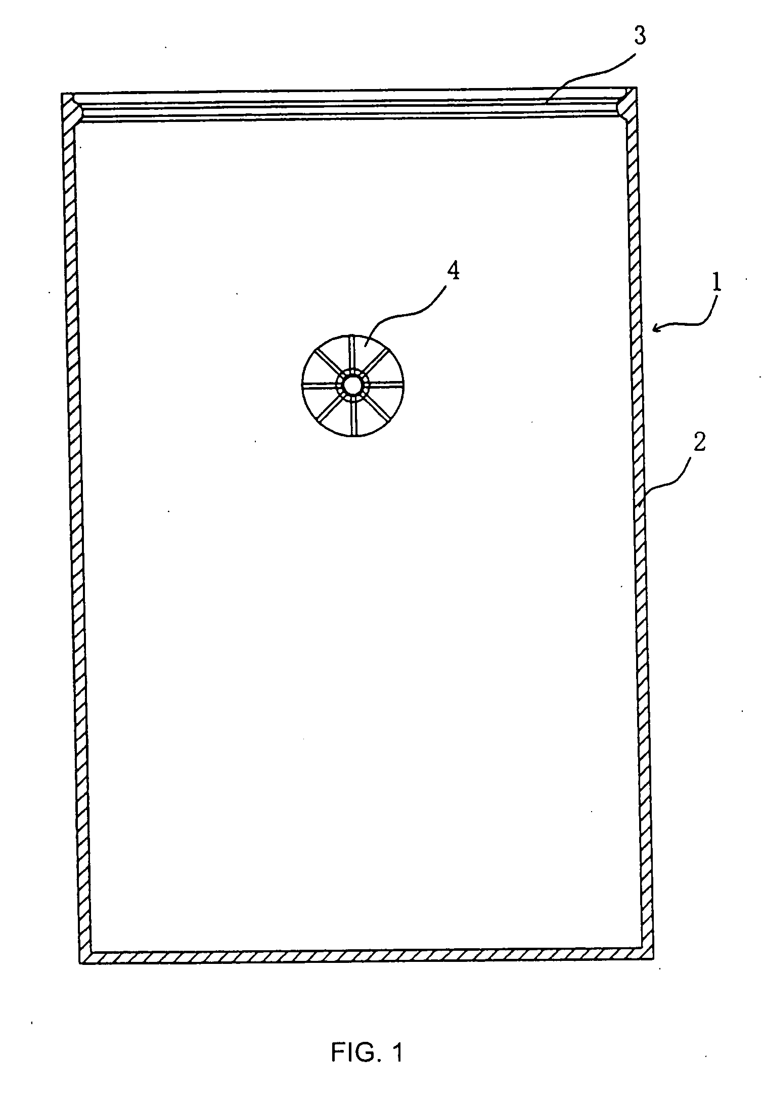
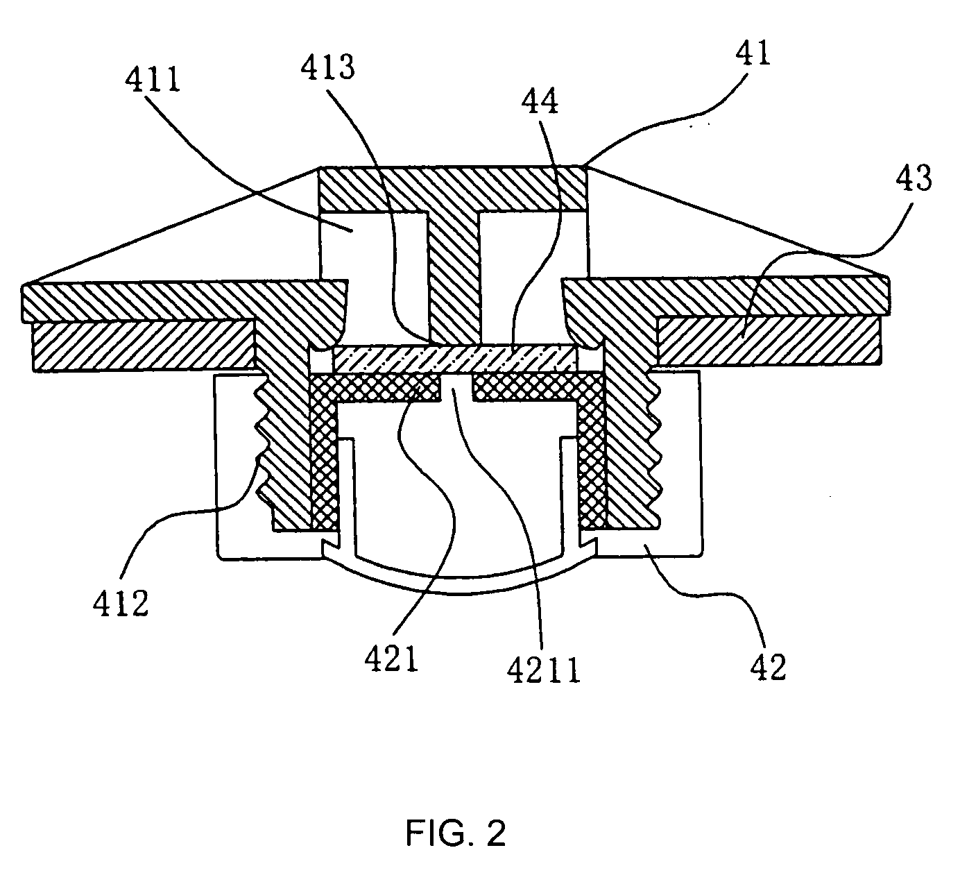
[0018] An example of the vacuum packaging bag of the invention is shown in FIGS. 1-4. The bag body 1 is made from plastic film. The bag body 1 has three sealed edges 2. One edge of the bag body is equipped with a concave-convex fastener 3. On the center of the bag body 1 is equipped a deflating device 4. The deflating device 4 consists of a base 41, a holding washer 43, a cover 42, and a sealing washer 44. The cover 42 and the base 41 are connected through screw threads. The main part of the base 41 is placed inside the bag body 1; the screw part 412 penetrates through one side of the bag body 1. The holding washer 42 is paced around the screw part 412 of the base 41 and fastens the film against the base 41. The sealing washer 44 is placed on a support 413. The support 413 is placed on the air passageway between the base 41 and the outside of the bag. In the middle of the cover 42, there is a pressure post 421 which is connected to the sealing washer 44. The sealing washer 44 is mad...

example 2

[0021] This example differs from Example 1 only in that the middle of the pressure post 421 has an opening 4211. Thus, when the cover 42 is slightly loosened, the air cannot flow through the base 41 and the cover 42, which makes impossible to deflate the bag 1.


PUM


Abstract

Disclosed is a vacuum packaging bag. Three edges of the bag are sealed and one edge is equipped with a concave-convex fastener. The bag is equipped with a deflating device. The deflating device consists of a base, a holding washer, a cover, and a sealing washer. The cover and the based are connected through screw threads. The base is placed inside the bag. The screw part of the base penetrates through one side of the bag. The holding washer fastens the film against the base. The sealing washer is placed on a support. The support is placed in the passageway between the base and the outside of the bag. The middle of the cover has a pressure post which is connected to the sealing washer. The middle of the pressure post has an opening to the outside of the bag. A deflating cylinder is used with the deflating device of the bag. The deflating cylinder is a piston cylinder. The front part of the piston rod has two holding boards. Between the holding boards there is a spacer. The backside board has a notch; the back part of the piston rod is connected to a pulling handle. On the front part of the cylinder is a convex. A pulling ring is attached to the convex. The vacuum packaging bag of the invention is simple in structure, easy to make, and convenient to use. It ensures the stored goods quality and value.

Description

FIELD OF THE INVENTION [0001] The invention relates to vacuum packaging. Particularly, the invention relates to vacuum packaging bags for food, medicine, camera, textile and electronic parts etc. The vacuum packaging bag of the invention is equipped with a deflating device. The invention also relates to a deflating cylinder which is used with the deflating device. BACKGROUND OF THE INVENTION [0002] The currently used vacuum packaging bags for food, medicine, and textile products are made from plastic films. After the goods are placed in the bag, the bag is then sucked out of air by vacuum and sealed. One problem the current technology has is that the vacuum pump is too burdensome to carry around. Also, vacuum pumps are expensive, which deprives the vacuum packaging from household uses. Moreover, the current vacuum packaging bags are not suitable for outdoor or filed operations. An example of such a time is when gathering samples or specimens where electricity required for the operat...

Claims


Application Information

Patent Timeline
IPC IPC(8): B65D33/01B65D33/16
CPCB65D33/2508B65D77/225B65D81/2023B65D81/2038Y10T137/7839
Inventor HAN, NGAI
Owner HAN NGAI
Why Eureka
Try Eureka