Imageable biopsy site marker

a biopsy site and marker technology, applied in the field of markers, can solve the problems of significantly reducing the mortality rate caused by this form of cancer, days or even a week before, and achieve the effects of accurate visualization of the boundary, easy or enhanced visualization of the biopsy cavity boundary, and accurate excise and remove a quantity

Inactive Publication Date: 2006-06-08
SENORX
View PDF78 Cites 114 Cited by
  • Summary
  • Abstract
  • Description
  • Claims
  • Application Information

AI Technical Summary

Benefits of technology

[0012] It is another object of the present invention to provide a biopsy site marker that does not migrate from the biopsy cavity even when the surrounding tissue is moved, manipulated or decompressed.
[0017] The present invention also provides chemical preparations and methods for marking biopsy sites, whereby a detectable marker (i.e., a substance or article that is detectable by imaging and / or palpation and / or visualization) is introduced into the cavity created by removal of a biopsy specimen (e.g., the “biopsy cavity”) such that (i) the marker will remain present and detectable at the biopsy at a first time point (e.g. 2 weeks after introduction), and (ii) the marker will clear sufficiently from the biopsy site, or will otherwise be undetectable by imaging so as not to interfere with follow-up imaging of the biopsy site and adjacent tissues at a second time point (e.g. typically 5-8 months and preferably at about 6 months after introduction).
[0033] Further in accordance with the invention, the detectable marker may comprise a) a detectable (e.g., imageable, palpable, energy-emitting and / or visible) substance that, if delivered alone into the cavity formed by removal of the biopsy specimen, would clear from such biopsy cavity so as to be no longer detectable at the first predetermined time point (e.g., two (2) weeks after introduction) in combination with b) a clearance limiting element (e.g., a diffusion-limiting polymer matrix, a membrane or liposomal encapsulation, a biodegradable matrix or encapsulant, etc . . . ) that will limit the dissolution, biodistribution and / or local metabolism of the detectable substance to remain present and detectable at the biopsy site for at least 2 weeks after introduction, but which will allow the detectable substance to be substantially cleared (e.g., dissolved, distributed from or locally metabolized) from the biopsy site at the second predetermined time point (e.g., 5-8 months and preferably at about 6 months after introduction).
[0039] Still further in accordance with the invention, there are provided methods for surgical excision of tissue that is located adjacent to or surrounding a biopsy cavity in which a visually detectable marker of the present invention has been delivered. The method generally comprises the steps of a) visualizing the perimeter of the visually discernible marker and b) excising tissue that lies adjacent to the perimeter of said visually discernible marker. This method of surgical excision may be used to accurately excise and remove a quantity of tissue of a specific width (e.g., a region or band that is 2 centimeters wide) that surrounds or lies adjacent to the original biopsy cavity. Because the biopsy site markers of the present invention actually occupy the original biopsy cavity, they serve to accurately mark the perimeter of that biopsy cavity. As such, the surgeon is able to accurately visualize the boundary of the biopsy cavity and to then excise and remove tissue that lies within a certain distance (e.g., 2 centimeters) of that cavity boundary. Such visualization of the biopsy cavity boundary may be made easier or enhanced when the biopsy site marker comprises, in addition to a visually discernible component such as a dye or carbon particles, a space-occupying bulking agent as described above in reference to palpable embodiments of the invention as the presence of such space occupying or bulking agent may serve to dilate or distend the biopsy cavity, thereby making it easier for the surgeon to visualize the boundaries of that biopsy cavity. This surgical excision method may be particularly suitable in cases where the histopathological evaluation of the biopsy specimen suggests that additional cancerous cells may continue to reside in tissue located within a certain distance of the original biopsy cavity boundary.

Problems solved by technology

Proper diagnostic procedures, frequent examination by well known techniques such as “mammography” and prompt subsequent surgical treatment have, however, significantly reduced the mortality rate caused by this form of cancer.
After the biopsy sample is taken, it may take several days or even a week before the results of the examination of the sample are obtained, and still longer before an appropriate treatment decision is reached.
However, due to the consistency of breast tissue and the fact that these biopsy site markers are typically introduced while the breast is still compressed between the mammography plates, these biopsy markers of the prior art may become attached to adjacent bands of connective tissue that do not remain at the specific location of the biopsy after the breast has been decompressed and removed from the mammography apparatus, and may suffer from additional disadvantages as well.

Method used


Image

  • Imageable biopsy site marker
  • Imageable biopsy site marker
  • Imageable biopsy site marker

Examples


Embodiment Construction

[0057] The following specification taken in conjunction with the drawings sets forth the preferred embodiments of the present invention. The embodiments of the invention disclosed herein are the best modes contemplated by the inventors for carrying out their invention in a commercial environment, although it should be understood that various modifications can be accomplished within the parameters of the present invention.

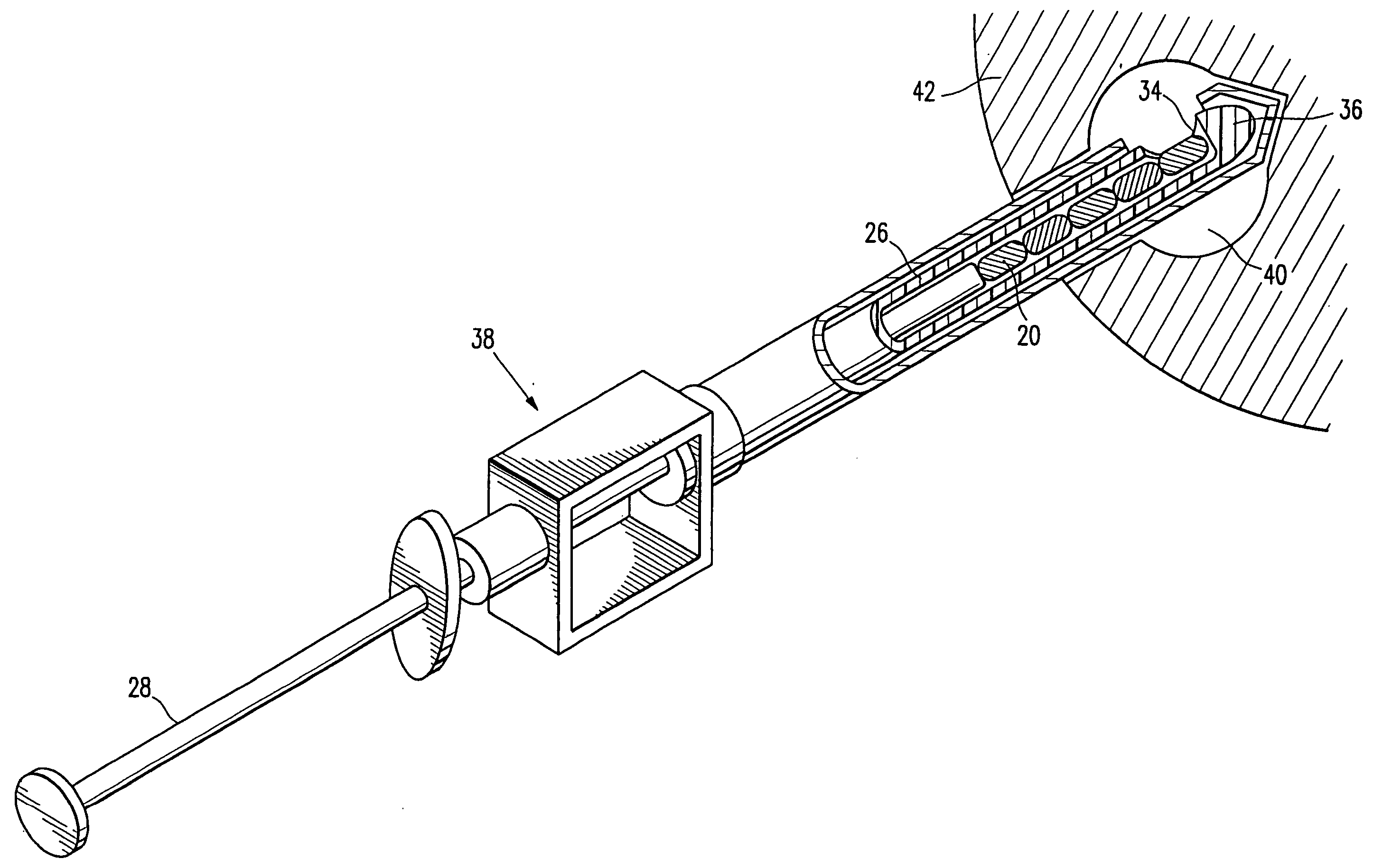
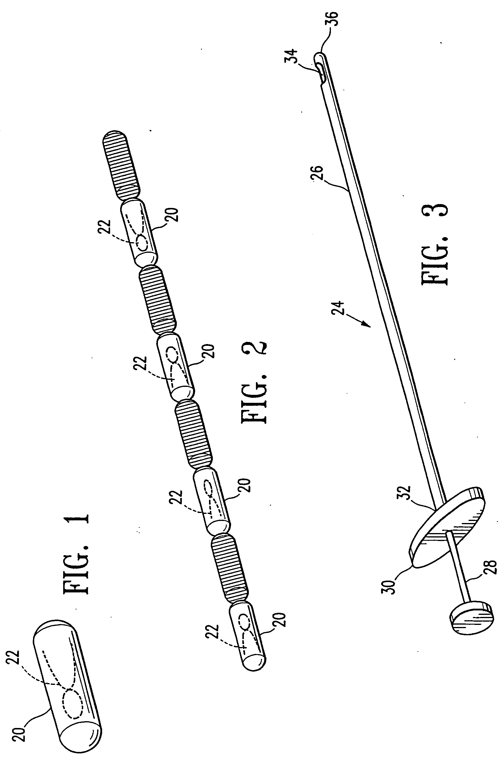
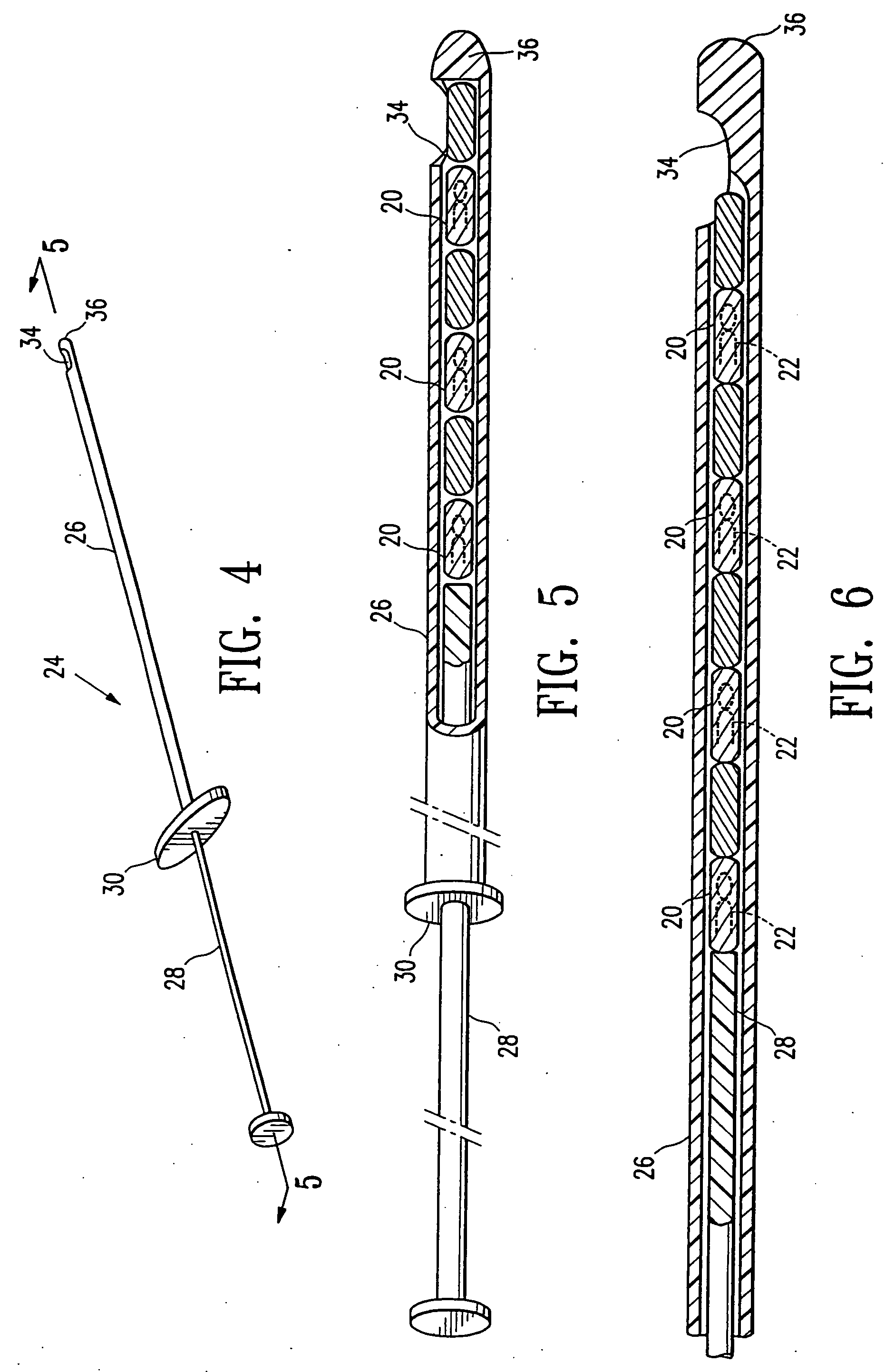
[0058] Referring now to the drawing figures and particularly to FIGS. 1 and 2, a body 20 of gelatin or reconstituted collagen in the shape of a pellet that includes or incorporates a radio-opaque marker 22 of a definite shape is disclosed. The gelatin or reconstituted collagen body 20 can be of virtually any shape or configuration, however the herein shown shape of a cylinder or pellet is preferred. The gelatin body of pellet 20 is of such size that several of the pellets can be deposited in a biopsy site, such as a typical biopsy site obtained by using the vacuum ...


PUM


Abstract

A biopsy site marker having at least one small marker body or pellet of bioresorbable material such as gelatin, collagen, polylactic acid, polyglycolic acid which has a radiopaque object, preferably with a non-biological configuration. The at least one bioresorbable body or pellet with a radiopaque object is deposited into the biopsy site, by an delivery device that includes an elongated tubular body with a piston slidable within the tubular body. One end of the tube is placed into the biopsy site. At least one but preferably several marker bodies or pellets are deposited sequentially into the biopsy site through the tube. At least the bioresorbable materials of the detectable markers remain present in sufficient quantity to permit detection and location of the biopsy site at a first time point (e.g., 2 weeks) after introduction but clear from the biopsy site or otherwise do not interfere with imaging of tissues adjacent the biopsy site at a second time point (e.g., 5-7 months) after introduction.

Description

RELATED APPLICATIONS [0001] This application is a continuation of application Ser. No. 10 / 719,448, filed on Nov. 21, 2003, which is a continuation of application Ser. No. 10 / 684,124, filed on Oct. 10, 2003, which is a continuation of application Ser. No. 10 / 001,043, filed on Oct. 31, 2001 (now U.S. Pat. No. 6,347,241), which is a continuation of application Ser. No. 09 / 343,975 (now U.S. Pat. No. 6,662,041), filed on Jun. 30, 1999, and a continuation-in-part application to application Ser. No. 09 / 241,936, filed on Feb. 2, 1999, now U.S. Pat. No. 6,161,034, which are incorporated herein by reference in their entirety.FIELD OF THE INVENTION [0002] The present invention is in the field of markers to be employed at biopsy sites to permanently mark the site, and to methods and apparatus for applying the permanent marker. More particularly, the present invention relates to a marker that is optimally adapted for marking biopsy sites in human breast tissue with permanently placed markers tha...

Claims


Application Information

Patent Timeline
Patent Type & Authority Applications(United States)
IPC IPC(8): A61B6/00A61B8/08A61B10/00A61B10/02A61B17/00A61B19/00A61K49/00
CPCA61B10/02A61B19/54A61B2017/00004A61B2019/5408A61B2019/5425A61B2019/5433A61B2019/545A61B2019/5487A61K49/006A61M37/0069A61B2090/3925A61B2090/3933A61B2090/395A61B2090/3987A61B90/39A61B2090/3908A61B2090/3929A61B2090/3788A61B2090/3975A61B2090/3995
Inventor BURBANK, FRED H.LUBOCK, PAULJONES, MICHAEL L.FORCIER, NANCY
Owner SENORX
Why Eureka
Try Eureka