Fixator for a fractured bone

a technology for fixing bones and fractures, applied in joint implants, medical science, surgery, etc., can solve the problems of wrist not being able to return to full mobility and strength, and the wrist may not be able to move and strength fully

Inactive Publication Date: 2006-06-08
KIRSCH JOHN M
View PDF12 Cites 17 Cited by
  • Summary
  • Abstract
  • Description
  • Claims
  • Application Information

AI Technical Summary

Problems solved by technology

Although the forearm 3, wrist 4 and hand 5 can be placed in a cast, this prolonged immobilization of the wrist 4 typically requires many weeks or months of expensive physical therapy, and the wrist may not return to full mobility and strength.
A problem with this fixator is that the wires are spaced apart at the clamp.
The fixator is prone to frequent bumps and jostles.
Another problem with the conventional fixator is its bulky and awkward size, weight and unattractive appearance.
The boxy shape of the clamp and wires are prone to bumps that do not glance off and impart significant force.
The projecting free ends of the wires can be easily snagged and pulled to cause pain and misalignment of the fixator.
The large bulky clamp and wires are also a constant visual reminder that can cause unwanted attention from others and emotional uneasiness to the patient, particularly at professional or formal engagements where the patient cannot easily conceal the fixator without attracting attention.
A further problem with the conventional fixator is its relatively high cost.
Replacing the clamp is difficult should it break or malfunction, such as via its screw stripping due to over tightening.
Maintaining an inventory of clampsis expensive.

Method used


Image

  • Fixator for a fractured bone
  • Fixator for a fractured bone
  • Fixator for a fractured bone

Examples


Embodiment Construction

[0027] While this invention may be embodied in many different forms, the drawings show and the specification describes in detail several preferred embodiments of the invention. It should be understood that the drawings and specification are to be considered exemplifications of the principles of the invention. They are not intended to limit the broad aspects of the invention to the embodiments illustrated.

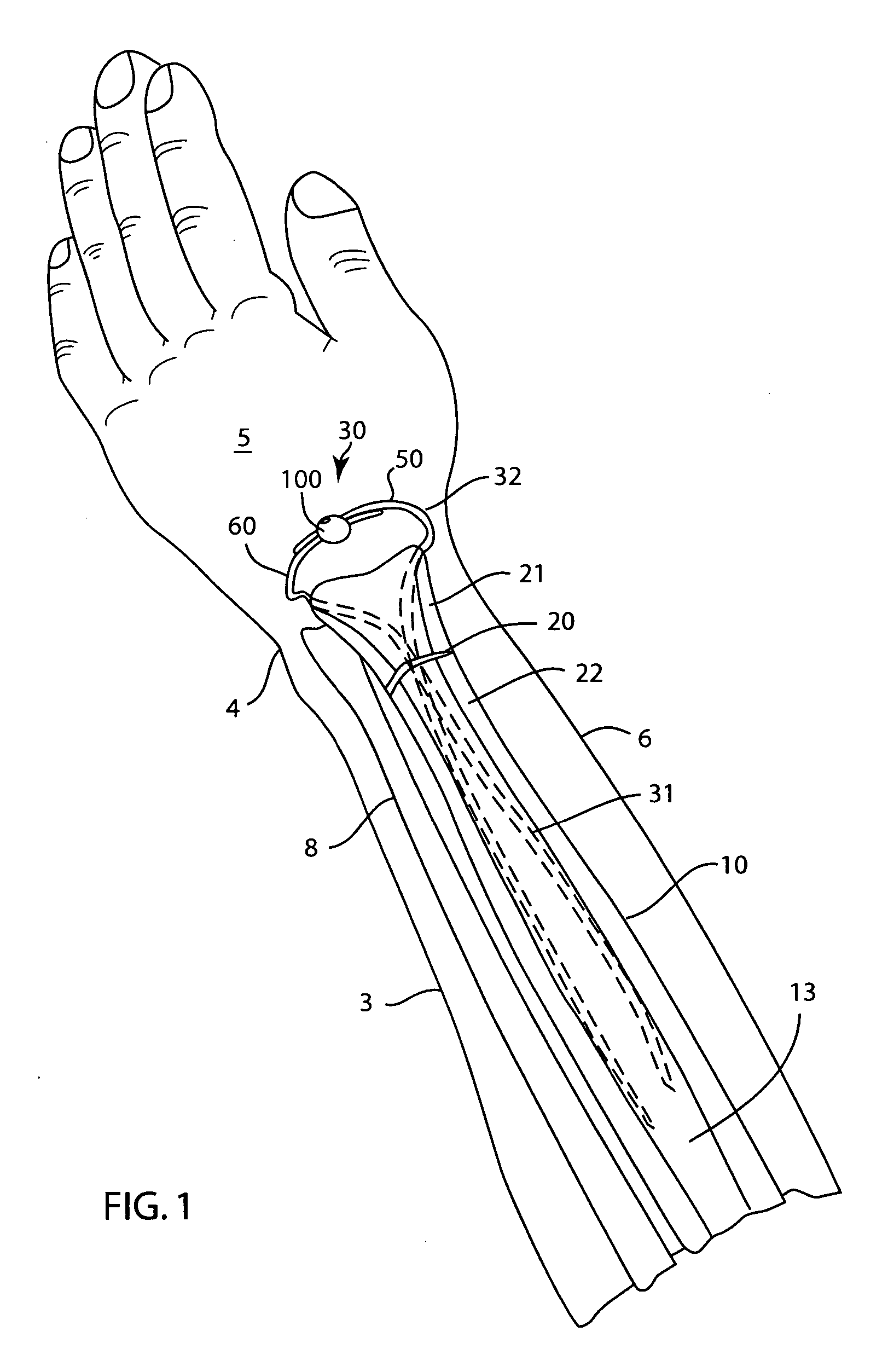
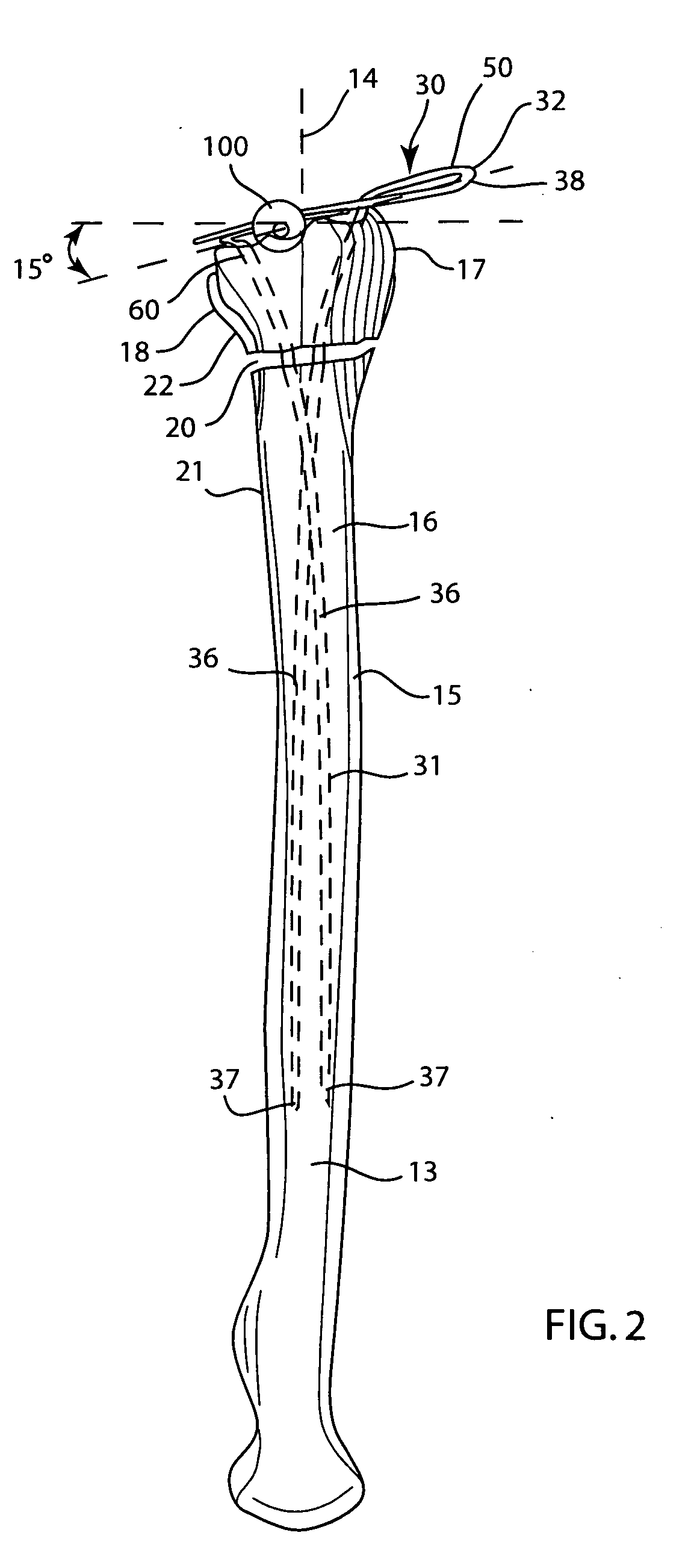
[0028] The human arm has a forearm 3, a wrist joint 4 and a hand 5 as shown in FIG. 1. The arm is formed by bones and soft tissues, such as muscle, tendons, veins, arteries, nerves, all of which are surrounded by a layer of skin 6 as shown in FIGS. 1 and 3. The two bones in the forearm 3 are the ulna 8 and the radius 10. Each bone 8 and 10 extend longitudinally along the length of the forearm 3 from the elbow (not shown) to the wrist 4, and is generally in side-by-side relation relative to the other bone. The ulna 8 is located along the outside or pinky finger side of the forearm 3...


PUM


Abstract

The present invention relates to a fixator for aligning and setting a fractured bone with an internal canal, such as a Colles' fracture of the radius. The fixator includes two positioning wires and at least one pinball fastener. An elongated portion of each wire is inserted through either the radial styloid process or the dorso-ulnar cortex and into the intramedullary canal. A shaped portion of each wire extends from the wrist. The lateral portion of the shaped portions are coplanar when viewed from above and their overlapping portions are in side-by-side relation when viewed from the side. The external portions are also preferably curved with concentric overlapping portions so that the fixator resembles a bracelet. When necessary, the fixator includes additional interfragmentary stabilizing wires that are securely joined to the positioning wires. Crimp sleeves can be used in conjunction with the pinballs to securely join the wires.

Description

BACKGROUND OF THE INVENTION [0001] One of the most common fractures caused by falling on the palm of the hand 5 is a break in the lower third of the radius bone 10 as shown in FIG. 1. This fracture 20 is commonly referred to as a Colles' fracture. The distal end 11 of the radius 10 joins the hand bones at the wrist 4. The distal end 11 has a generally concave, or partial cup shaped surface. When viewed from above as in FIG. 2, the surface forming the distal end 11 is generally angled about 15 degrees (15°) out of normal from a longitudinal axis 14 of the radius 10. The thumb side extends further forward. Similarly, the top and bottom portions extend further forward than the central portion. This cup-shaped surface is aligned with the longitudinal axis 14 to face forward toward the wrist 4. This structure helps give the wrist 4 its full range of mobility and added strength. When the distal end 11 is broken, proper alignment and setting of the pieces 21 and 22 of bone 10 is important ...

Claims


Application Information

Patent Timeline
Patent Type & Authority Applications(United States)
IPC IPC(8): A61B17/56
CPCA61B17/60A61B17/6425A61B17/645A61B17/82A61B2019/444A61B90/92
Inventor KIRSCH, JOHN M.
Owner KIRSCH JOHN M
Why Eureka
Try Eureka