Systems and methods for stabilizing the motion or adjusting the position of the spine

a motion stabilization and spine technology, applied in the field of spinal disorders and pain, can solve the problems of affecting the ability of spinal motion segments to properly function, eventual deterioration or disorder, and debilitating pain, and achieve the effect of low profile and greater profil

Active Publication Date: 2006-06-08
THE BOARD OF TRUSTEES OF THE LELAND STANFORD JUNIOR UNIV
View PDF101 Cites 466 Cited by
  • Summary
  • Abstract
  • Description
  • Claims
  • Application Information

AI Technical Summary

Benefits of technology

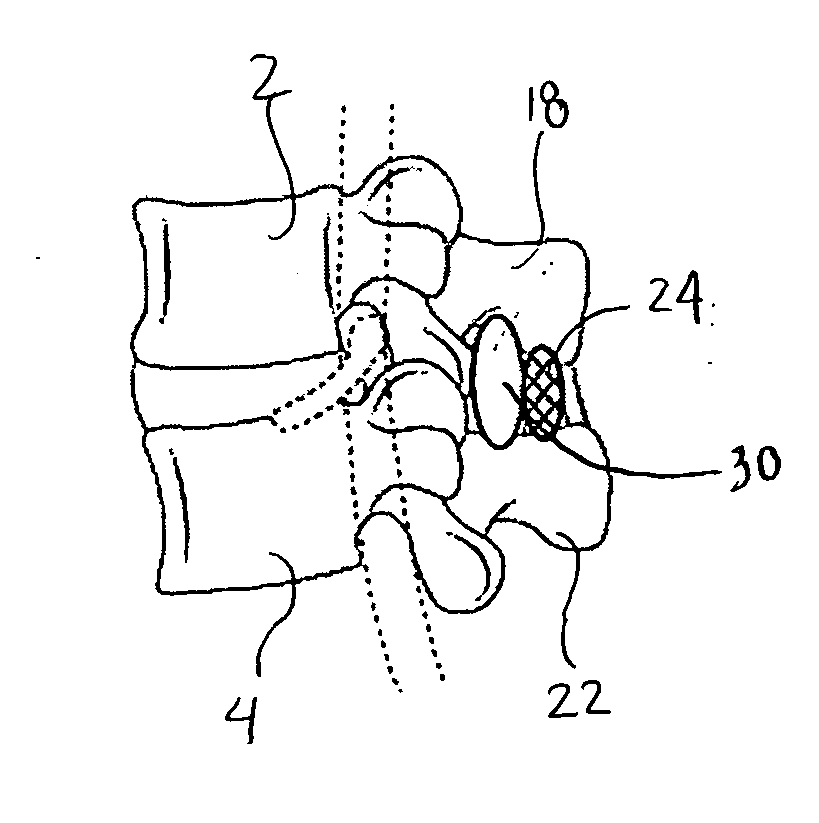
[0024] The expandable lateral members of the present invention have an unexpanded configuration and an expanded configuration, wherein the expandable member in an expanded configuration has a size, volume and / or shape configured for positioning minimally invasively in a position lateral to a spinous process. The expandable member may include an enclosed cavity which is fillable with a material to effect expansion or may have a strut or scaffolding-like structure that has a low profile configuration for delivery purposes through a small working channel and which is expandable to a greater profile upon deployment at or in close proximity to the implant site.

Problems solved by technology

Traumatic, inflammatory, metabolic, synovial, neoplastic and degenerative disorders of the spine can produce debilitating pain that can affect a spinal motion segment's ability to properly function.
Often, a disorder in one location or spinal component can lead to eventual deterioration or disorder, and ultimately, pain in the other.
While spine fusion generally helps to eliminate certain types of pain, it has been shown to decrease function by limiting the range of motion for patients in flexion, extension, rotation and lateral bending.
Furthermore, the fusion creates increased stresses on adjacent non-fused motion segments and accelerated degeneration of the motion segments.
Additionally, pseudarthrosis (resulting from an incomplete or ineffective fusion) may not provide the expected pain-relief for the patient.
Also, the device(s) used for fusion, whether artificial or biological, may migrate out of the fusion site creating significant new problems for the patient.
Unfortunately, the currently available artificial discs do not adequately address all of the motion mechanics of the spinal column.
It has been found that the facet joints can also be a significant source of spinal disorders and debilitating pain.
Current interventions for the treatment of facet joint disorders have not been found to provide completely successful results.
Facetectomy (removal of the facet joints) may provide some pain relief; but as the facet joints help to support axial, torsional, and shear loads that act on the spinal column in addition to providing a sliding articulation and mechanism for load transmission, their removal inhibits natural spinal function.
Laminectomy (removal of the lamina, including the spinal arch and the spinous process) may also provide pain relief associated with facet joint disorders; however, the spine is made less stable and subject to hypermobility.
Problems with the facet joints can also complicate treatments associated with other portions of the spine.
In fact, contraindications for disc replacement include arthritic facet joints, absent facet joints, severe facet joint tropism, or otherwise deformed facet joints due to the inability of the artificial disc (when used with compromised or missing facet joints) to properly restore the natural biomechanics of the spinal motion segment.
While various attempts have been made at facet joint replacement, they have been inadequate.
This is due to the fact that prosthetic facet joints preserve existing bony structures and therefore do not address pathologies that affect facet joints themselves.
As the lamina is a very complex and highly variable anatomical structure, it is very difficult to design a prosthesis that provides reproducible positioning against the lamina to correctly locate the prosthetic facet joints.
In addition, when facet joint replacement involves complete removal and replacement of the natural facet joint, as disclosed in U.S. Pat. No. 6,579,319, the prosthesis is unlikely to endure the loads and cycling experienced by the vertebra.
Thus, the facet joint replacement may be subject to long-term displacement.
Furthermore, when facet joint disorders are accompanied by disease or trauma to other structures of a vertebra (such as the lamina, spinous process, and / or transverse processes) facet joint replacement is insufficient to treat the problem(s).
While this system is able to provide load sharing and restoration of disc height, because it is so rigid, it does not effective in preserving the natural motion of the spinal segment into which it is implanted.
Because these types of systems require the use of pedicle screws, implantation of the systems are often more invasive to implant than interspinous spacers.

Method used


Image

  • Systems and methods for stabilizing the motion or adjusting the position of the spine
  • Systems and methods for stabilizing the motion or adjusting the position of the spine
  • Systems and methods for stabilizing the motion or adjusting the position of the spine

Examples


Embodiment Construction

[0056] Before the subject devices, systems and methods are described, it is to be understood that this invention is not limited to particular embodiments described, as such may, of course, vary. It is also to be understood that the terminology used herein is for the purpose of describing particular embodiments only, and is not intended to be limiting, since the scope of the present invention will be limited only by the appended claims.

[0057] Unless defined otherwise, all technical and scientific terms used herein have the same meaning as commonly understood by one of ordinary skill in the art to which this invention belongs.

[0058] It must be noted that as used herein and in the appended claims, the singular forms “a”, “an”, and “the” include plural referents unless the context clearly dictates otherwise. Thus, for example, reference to “a spinal segment” may include a plurality of such spinal segments and reference to “the screw” includes reference to one or more screw and equival...


PUM


Abstract

The present invention provides systems and methods for stabilizing or adjusting the position of at least one spinal motion segment.

Description

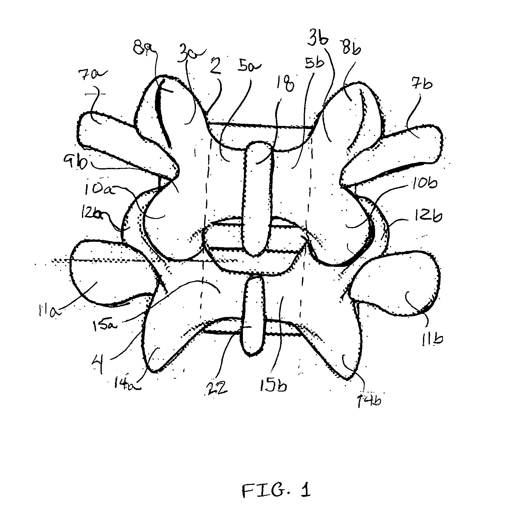
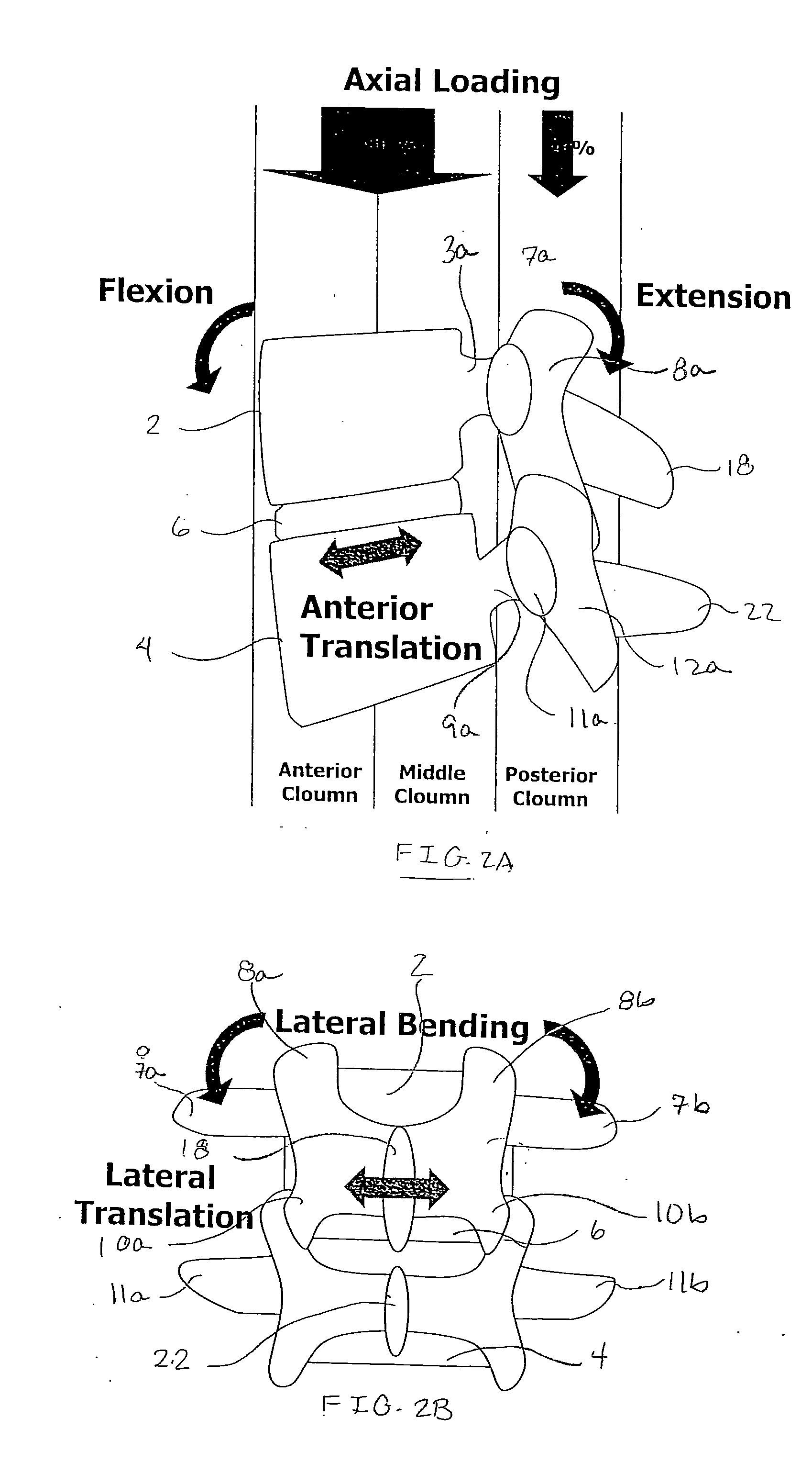
FIELD OF THE INVENTION [0001] The present invention is directed towards the treatment of spinal disorders and pain. More particularly, the present invention is directed to systems and methods of treating the spine to eliminate pain, adjust the position of one or more spinal motion segments and / or enable spinal motion which effectively mimics that of a normally functioning spine. BACKGROUND OF THE INVENTION [0002]FIG. 1 illustrates a portion of the human spine having a superior vertebra 2 and an inferior vertebra 4, with an intervertebral disc 6 located in between the two vertebral bodies. The superior vertebra 2 has superior facet joints 8a and 8b, inferior facet joints 10a and 10b, and spinous process 18. Pedicles 3a and3b interconnect the respective superior facet joints 8a, 8b to the vertebral body 2. Extending laterally from superior facet joints 8a, 8b are transverse processes 7a and 7b, respectively. Extending between each inferior facet joints 10a and 10b and the spinous proc...

Claims


Application Information

Patent Timeline
Patent Type & Authority Applications(United States)
IPC IPC(8): A61B17/58
CPCA61B17/3468A61B2017/0256A61B2017/00557A61B17/7065A61B17/025A61B17/7064A61B17/7067
Inventor KIM, DANIEL H.
Owner THE BOARD OF TRUSTEES OF THE LELAND STANFORD JUNIOR UNIV
Why Eureka
Try Eureka