Variable valve control apparatus for internal combustion engine

Inactive Publication Date: 2006-06-15
DENSO CORP
View PDF1 Cites 17 Cited by
  • Summary
  • Abstract
  • Description
  • Claims
  • Application Information

AI Technical Summary

Benefits of technology

[0011] The present invention operates a control input of the variable valve apparatus so that a difference between the output of the reference model and the valve timing of the variable valve apparatus is made small, thus compensating for variations in responsiveness of the variable valve control caused by variations in performance of the variable valve apparatus. In addition, since there is the feature that variations in a changing speed of the valve timing of the variable valve apparatus get small in the region of a maximum changing speed of the valve timing of the variable valve apparatus, when the variable valve apparatus is controlled by using the region of the maximum changing speed of the valve timing with priority, it becomes possible to control even the variable valve apparatus as the

Problems solved by technology

There is, however, a problem with an occurrence of variations in responsiveness of variable valve control caused by variations in the manufacture of the variable valve apparatus or variations in performance of the vari

Method used


Image

  • Variable valve control apparatus for internal combustion engine
  • Variable valve control apparatus for internal combustion engine
  • Variable valve control apparatus for internal combustion engine

Examples


Example

[0022] A preferred embodiment of the present invention will be hereinafter explained with reference to the drawings.

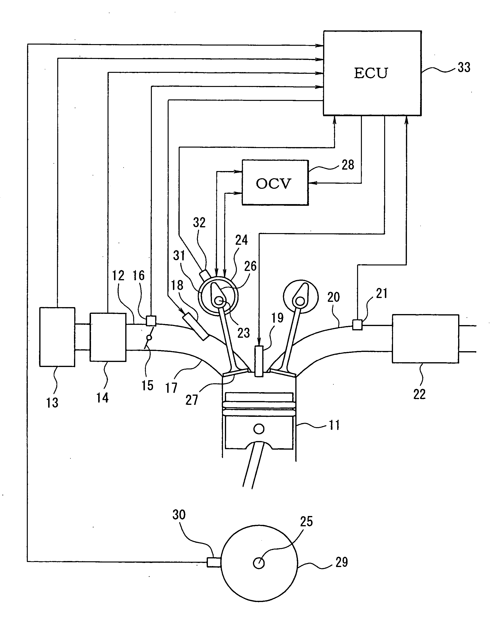
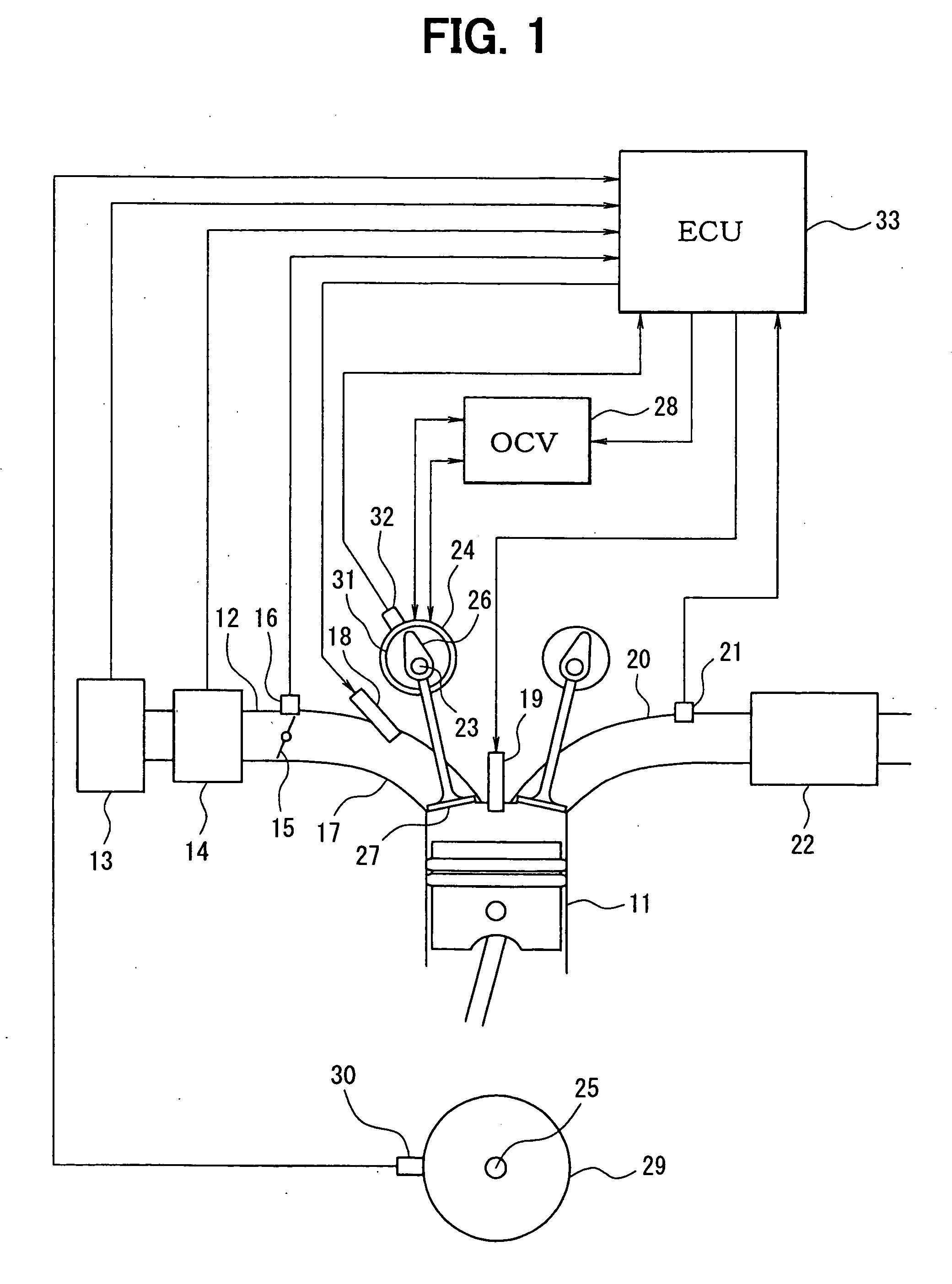
[0023] Firstly, a schematic arrangement of an entire engine control system will be explained with reference to FIG. 1. An air cleaner 13 is disposed in the most upstream portion of an intake pipe 12 for an engine 11 as an internal combustion engine and an air-flow meter 14 for detecting an intake air quantity is disposed in the downstream side of the air cleaner 13. A throttle valve 15 an opening of which is adjusted by a motor or the like and a throttle opening sensor 16 for detecting the opening (throttle opening) of the throttle valve 15 are disposed in the downstream side of the air-flow meter 14.

[0024] A fuel injection valve 18 is mounted in the vicinity of an intake port of an intake manifold 17 introducing air into each cylinder of the engine 11. Further, an ignition plug 19 is mounted in a cylinder head of the engine 11 for each cylinder and a mixture in the ...


PUM


Abstract

A reference model simulates a desired response characteristic of the variable valve timing apparatus and is constructed by using a dynamic characteristic in a region of the maximum changing speed of the valve timing of the variable valve timing apparatus. The variable valve timing apparatus is constructed of the control system with two degrees of freedom in which in the controller, the feedback duty is calculated so that the deviation between the output obtained by applying the time delay to the output of the quickest response model and the valve timing is small, and in the reverse VCT model, the feed forward duty is calculated so that the target advance amount is realized based upon the output of the quickest response model, and the control duty of the variable valve timing apparatus is obtained by addition of the feedback duty and the feed forward duty.

Description

CROSS-REFERENCE TO RELATED APPLICATION [0001] This application is based on Japanese Patent Application No. 2004-363506 filed on Dec. 15, 2004, the disclosure of which is incorporated herein by reference. FIELD OF THE INVENTION [0002] The present invention relates to a variable valve control apparatus for an internal combustion engine in which a variable valve apparatus for changing valve opening / closing characteristics of an intake valve or an exhaust valve is a control object. BACKGROUND OF THE INVENTION [0003] There has been recently increasing an in-vehicle internal combustion engine using a variable valve apparatus which changes valve opening / closing characteristics such as valve timing or a valve lift amount of an intake valve or an exhaust valve for the purpose of a power output improvement, a fuel economy improvement, reduction of exhaust emissions and the like. There is, however, a problem with an occurrence of variations in responsiveness of variable valve control caused by...

Claims


Application Information

Patent Timeline
IPC IPC(8): F01L1/34
CPCF01L1/344F01L13/0015F01L2001/0537F01L2800/00F02D13/0207F02D13/0238F02D41/1401F02D2041/001F02D2041/141F02D2041/1431F02D2041/1433F02D2041/1434Y02T10/18Y02T10/12
Inventor SHIKATA, YASUHIROKITA, MASAYUKI
Owner DENSO CORP
Why Eureka
Try Eureka