Laryngeal mask airway device

a technology of airway device and laryngeal mask, which is applied in the direction of life-saving devices, respiratory apparatus, trachea tubes, etc., can solve the problems of unwanted resistance to airflow and the inability to prevent obstruction of the bars described abov

Inactive Publication Date: 2006-06-15
TELEFLEX LIFE SCI PTE LTD
View PDF12 Cites 35 Cited by
  • Summary
  • Abstract
  • Description
  • Claims
  • Application Information

AI Technical Summary

Benefits of technology

[0010] The present invention has as its overall objective to provide an LMA device of the types described above, i.e., incorporating means for draining gastric discharge from the region of the oesophageal inlet of the patient, which substantially avoids the disadvantages described above in relation to various of the known types of LMA-devices.

Problems solved by technology

These bars proved effective in preventing epiglottis obstruction but offered unwanted resistance to airflow and tended to obstruct passage of suction or inspection tubing.
The paired bars described above were not able to prevent obstruction occurring as a result of the epiglottic rim lying in contact with the bowl or floor of the mask.

Method used


Image

  • Laryngeal mask airway device
  • Laryngeal mask airway device
  • Laryngeal mask airway device

Examples


second embodiment

[0068]FIGS. 18 and 19 show the backplate 27b. Parts in FIGS. 18 and 19 having corresponding parts in FIGS. 16 and 17 have the same reference numeral with the addition of suffix b. The backplate 27b is similar to the backplate 27 illustrated in FIGS. 16 and 17 except that the backplate 27b does not a strap similar to strap 100.

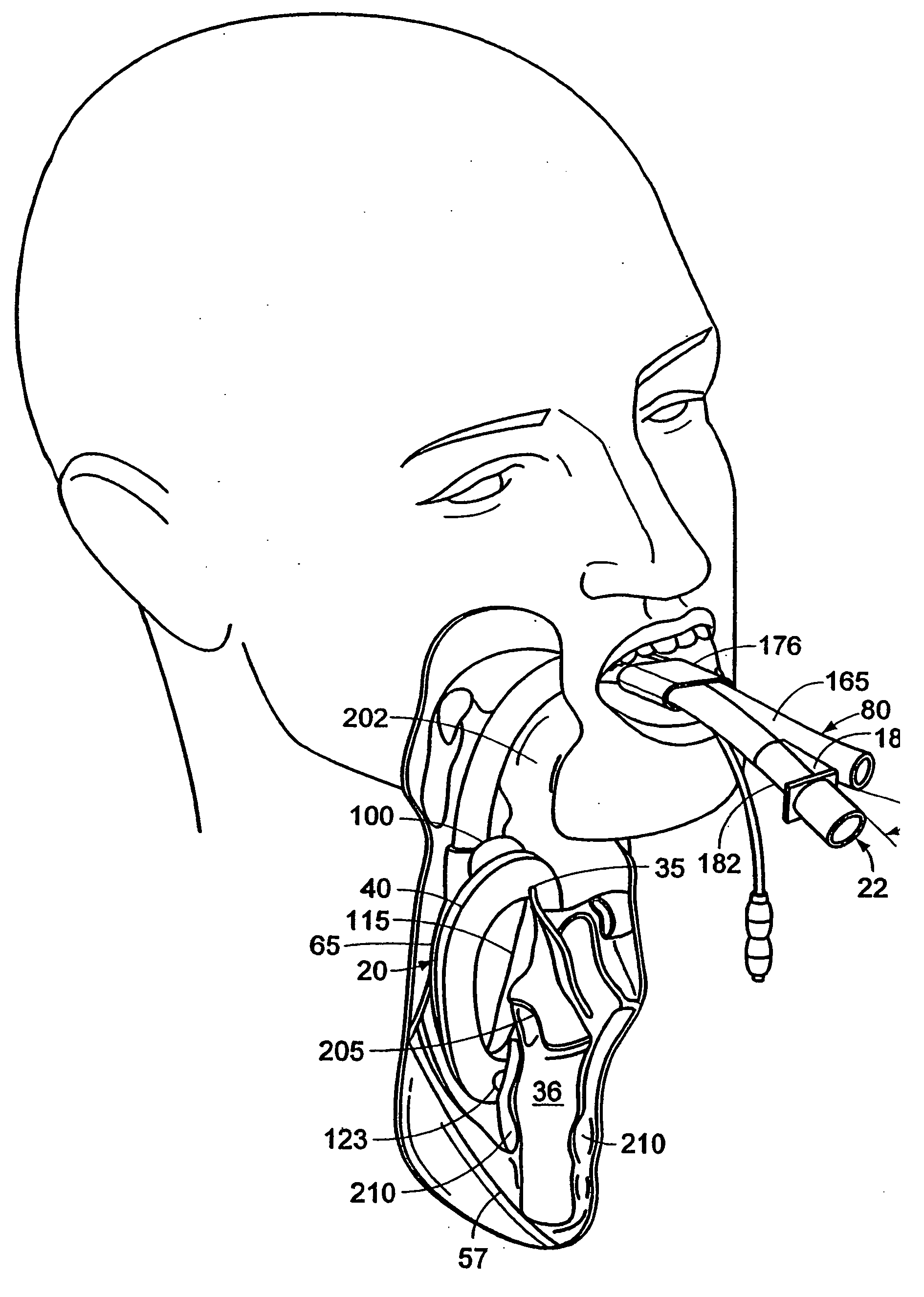
[0069] The evacuation tube 80 comprises an internal-drain tube 115 extending between the tube-joint 92 and the distal region 45 of the main-cuff 40 on the laryngeal-side 81 of the backplate 27. The internal-drain tube 115 longitudinally traverses the interior of the distal region 45 of the main-cuff 40 in sealed relation therewith for operative engagement and communication with the inlet of the oesophagus 57. The internal-drain tube 115 is anterior relative to the seam 85 of the main-cuff 40 such that the seam is disposed between the internal-drain tube and the distal end of the oval portion 87.

[0070] The internal-drain tube 115 therefore pierces the distal re...

third embodiment

[0113]FIGS. 23 and 24 illustrate the LMA-device 20c. Parts in FIGS. 23 and 24 having corresponding parts in FIGS. 1 to 22 have the same reference numeral with the addition of suffix c. The main-cuff 40c may have soft and yielding ridges (not shown) bilaterally disposed on the anteriorly-facing distal region 45c of the main-cuff which are suitably contoured to fill the anatomical grooves known as the pyriform fossae to increase the sealing efficacy of the main-cuff. The LMA-device 20c exploits the triangular cross-section of the grooves of the pyriform fossae which are roofed over and isolated by the anterior surface of the main-cuff 40c bilaterally. The entire length of the grooves of the pyriform fossae are covered by the main-cuff 40c such that a respective cavity is defined by each groove and the contiguous portion of the anterior surface of the main-cuff. Incorporation of one or more one-way valves 215, such as a reed or duck-bill valve, in the anterior wall of the main-cuff 40c...


PUM


Abstract

A laryngeal-mask airway device including provision for drainage of the oesophagus comprises an inflatable main-cuff and a backplate having a laryngeal-side and a pharyngeal-side. The backplate also has an external tube-joint adjacent to the proximal region of the main-cuff. The backplate is hermetically bonded to the periphery of the main-cuff establishing separation between a laryngeal-chamber region and a pharyngeal region. An distally open evacuation tube includes a distal portion which longitudinally traverses the interior of the distal region of the main-cuff in sealed relation therewith for operative engagement and communication with the inlet of the oesophagus. The evacuation tube traverses the laryngeal-chamber region generally adjacent to the laryngeal-side of the backplate and passages through a proximally located tube-joint to the pharyngeal region. An airway tube also extends into the tube-joint for communication with an airway port to provide a flowpath between the airway tube and laryngeal-chamber region.

Description

CROSS-REFERENCE SECTION [0001] This application is a continuation of currently pending U.S. patent application Ser. No. 10 / 225,678, filed Aug. 22, 2002, which is a continuation of U.S. patent application Ser. No. 09 / 289,319, filed Apr. 9, 1999, now U.S. Pat. No. 6,439,232. This application also claims the benefit of United Kingdom patent application 9817537.5, filed Aug. 13, 1998.BACKGROUND OF THE INVENTION [0002] This invention relates to laryngeal mask airway devices (LMA-devices). Such devices are useful in facilitating lung ventilation in unconscious patients by forming a low pressure seal around the patient's laryngeal inlet, avoiding the known harmful effects of the endotracheal tube, which forms a seal within the windpipe (trachea). [0003] LMA-devices of the types disclosed in UK Patent Nos. 2111394 and 2205499 have become accepted items of equipment for rapidly and reliably establishing an unobstructed airway in a patient in emergency situations and in the administration of ...

Claims


Application Information

Patent Timeline
Patent Type & Authority Applications(United States)
IPC IPC(8): A62B9/06A61M16/00A61M16/04
CPCA61M16/04A61M16/0409A61M16/0415A61M16/0486A61M16/208A61M16/0447A61M16/0463A61M16/0497A61M16/0493A61M16/0445A61M16/0434A61M16/0443
Inventor BRAIN, ARCHIBALD IAN JEREMY
Owner TELEFLEX LIFE SCI PTE LTD
Why Eureka
Try Eureka