
Monitoring of wearing surface layer thickness

Inactive Publication Date: 2006-06-15
IBM CORP
View PDF3 Cites 45 Cited by
  • Summary
  • Abstract
  • Description
  • Claims
  • Application Information

AI Technical Summary

Benefits of technology

[0008] The present invention provides a product comprising a wearing surface layer and at least one Radio Frequency IDentification (RFID) tag within a thickness of the wearing surface layer, the wearing

Problems solved by technology

Tires that are driven under-inflated generate excessively high heat levels that can weaken the tire to the point of failure.
At high speed, a rapidly deflating tire can cause loss of vehicle control.
An over-inflated tire will result in harsh ride quality and will cause uneven tire wear.
Furthermore, operating a vehicle with over- or under-inflated tires increases both fuel consumption and the exhaust emissions produced by the vehicle.
The treads that accomplishes this wear out over time.
As a consequence, the distance that is required to stop a vehicle increase with the wear of tires.
Other known marking devices disappear when the wear of the treads becomes critical.
However, a main drawback of these systems is that wear of tires must be done wheel after wheel, when the vehicle is stopped, according to a manual or visual analysis that is often painful due to the location of the wheels in the vehicle wings.
If such solution allows an automatic control of the tire wear, it closely depends upon the vehicle environment and driving conditions and therefore, it could be complex to implement.

Method used


Image

  • Monitoring of wearing surface layer thickness
  • Monitoring of wearing surface layer thickness
  • Monitoring of wearing surface layer thickness

Examples


first embodiment

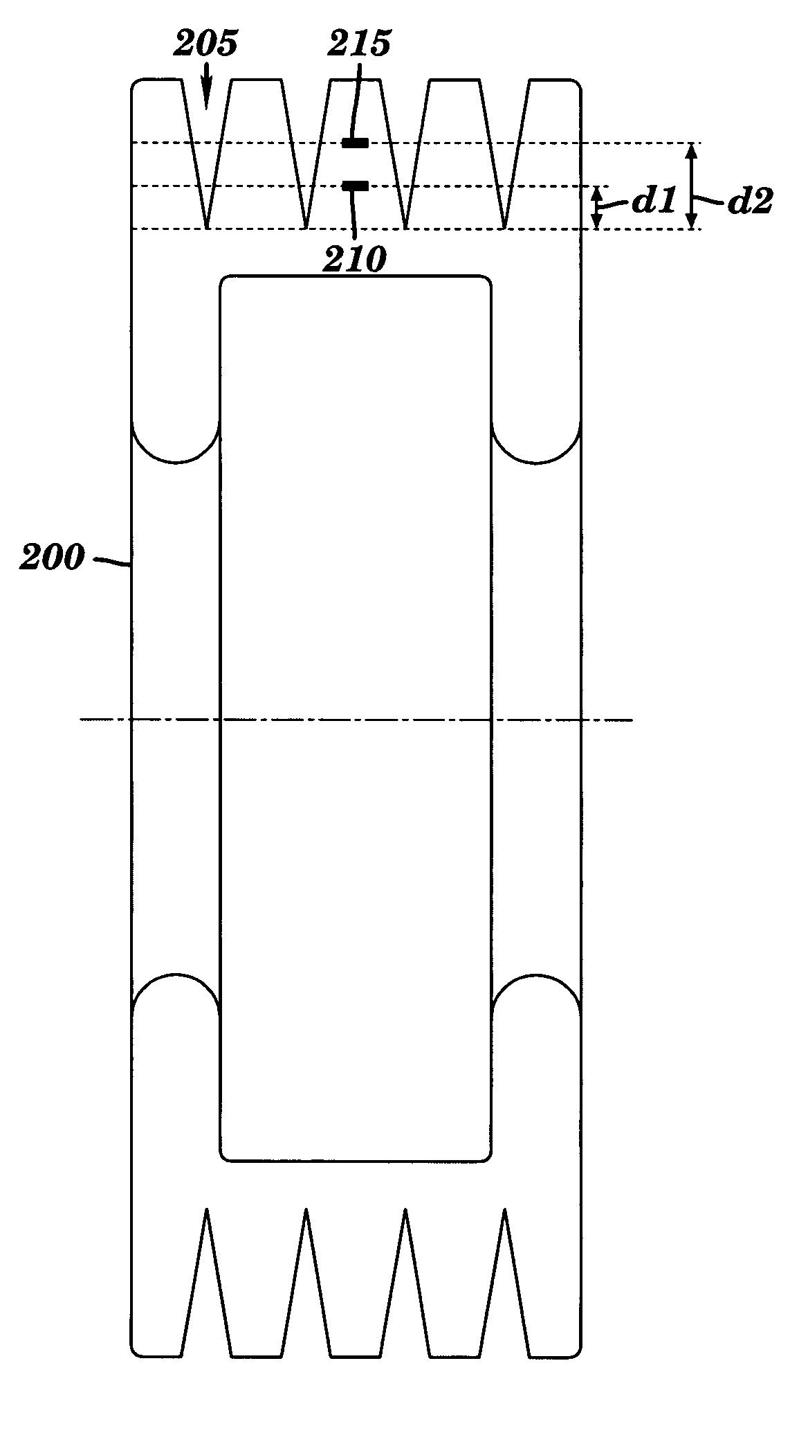
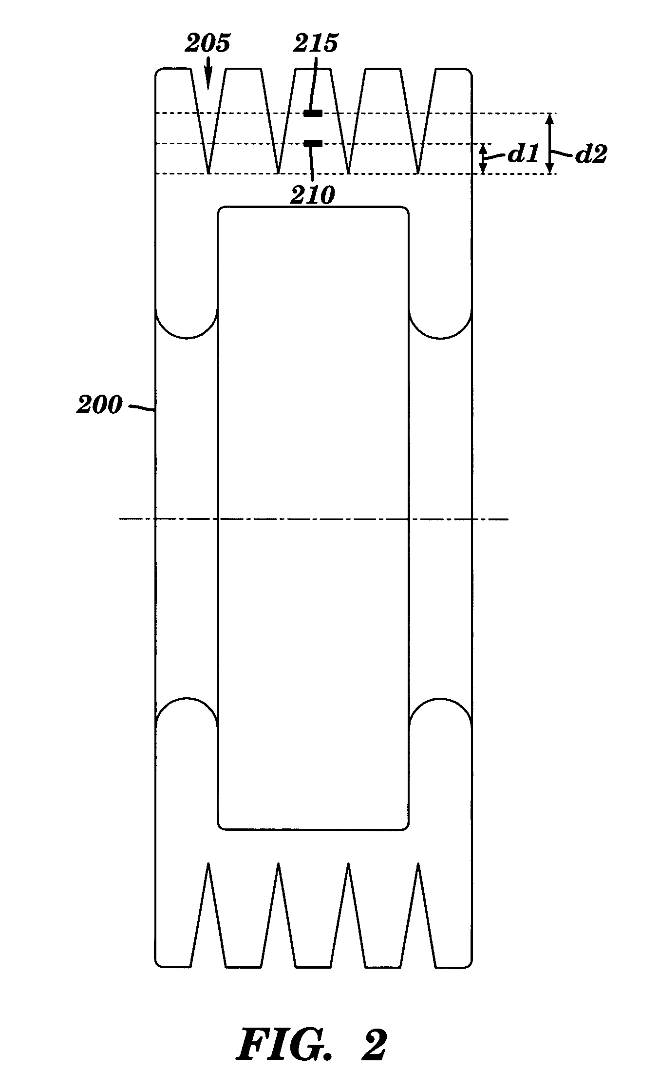
[0039] In the present invention, the tire tread or surface to monitor comprises at least one RFID corresponding to at least one wear threshold. The wear level is given by the presence or absence of this at least one RFID. If several RFIDs are embedded within the tire tread or surface to monitor, the data contained in each of them must be different so that the presence of each RFID can be detected.

[0040]FIG. 2 depicts a cross section view of an example of a tire 200 having grooves 205 designed in the tire tread. The tire 200 comprises a first RFID 210 located at a distance d1 from the bottom of the grooves and a second RFID 215 located at a distance d2 from the bottom of the grooves. In this example, the RFIDs are inserted within the rubber mix but it must be understood that RFIDs can also be positioned and glued within the grooves. For sake of illustration, d1 is equal to the minimum legal treads (i.e., 1.6 mm), and d2 is equal to 3 mm which corresponds to a main change of the tire ...

second embodiment

[0056] The algorithms presented on FIGS. 4a and 4b, described supra, are also valid for this However, the values N and N(i) are not stored in the reader memory but are directly determined from the values stored in the detected RFIDs. Considering that values stored in the RFIDs are expressed as V(j), where j is an index corresponding to the rank of the RFIDs within a tire. Then,

N=maxj(V(j))  (4)

[0057] Likewise, considering that values stored in the RFIDs are expressed as V(i,j), where i is the index corresponding to the tire i, and j is the index corresponding to the rank of the RFIDs within the tire then,

N(i)=maxj(V(i,j))  (5)

[0058] In a third embodiment of the present invention, a particular RFID (e.g., the RFID that is located at the greatest distance from the periphery of the tire; i.e., the maximum distance from the exterior surface of the tire tread) is used to store additional information. Firstly, this additional information is the number of RFIDs that were embedded withi...

fourth embodiment

[0059] In the present invention, several RFIDs are distributed along the tire width, at approximately the same distance from the tire periphery, so as to control wear balance along the tire width. The tire width is oriented perpendicular to the tire thickness and perpendicular to the opposite sides of the tire. FIG. 6 shows an example of such a distribution of RFIDs along the tire width. As illustrated, a first set 508A of RFIDs (0-0 to 0-5) is embedded within the rubber in the tire left part and a second set 508B of RFIDs (1-0 to 1-5) is embedded within the rubber of the tire right part. By counting and comparing the number of RFIDs embedded within each set of the tire, one can determine if the tire wear is normal or abnormal (i.e., one can analyze tire wear balance along the tire width). For example, if the number of RFIDs belonging to each set is the same for all the sets or if there is only a difference of one RFID, one can conclude that the tire wear is a normal wear (i.e., the...


PUM


Abstract

A method and associated product for wear level determination. Data is received from at least one Radio Frequency IDentification (RFID) tag within a thickness of a wearing surface layer of each product of at least one product. The wearing surface layer of each product is an outermost surface layer of each product. The wearing surface layer of each product is adapted to be worn away such that the thickness of the wearing surface layer is reduced as each product is being used. A measure of wear of the wearing surface layer of each product is determined.

Description

BACKGROUND OF THE INVENTION [0001] 1. Technical Field [0002] The present invention relates to a method, system, and product for monitoring of wearing surface layer thickness. [0003] 2. Related Art [0004] Because tires are the only points of contact between a vehicle and the road, tires are one of the most crucial safety components in the vehicle, for all types of vehicles, such as cars, trucks, sport utility vehicles, off-road vehicles, airplanes, motorcycles, bicycles, mobile industrial and construction equipment, and the like. Tires are responsible for how the vehicle responds to the driving and steering. To optimize the effects of the tires on the road and therefore, to provide a safety behavior of the vehicle, the inflation pressure of the tires must be kept within the range given by the manufacturer. Tires that are driven under-inflated generate excessively high heat levels that can weaken the tire to the point of failure. At high speed, a rapidly deflating tire can cause loss ...

Claims


Application Information

Patent Timeline
IPC IPC(8): B60C11/24
CPCY10T152/10027B60C11/24
Inventor BAUCHOT, FREDERICMARMIGERE, GERARD
Owner IBM CORP
Features
  • Generate Ideas
  • Intellectual Property
  • Life Sciences
  • Materials
  • Tech Scout
  • Unparalleled Data Quality
  • Higher Quality Content
  • 60% Fewer Hallucinations
Learn More