
Welding-type power supply with a state-based controller

a technology of state-based control and power supply, which is applied in the direction of welding apparatus, arc welding apparatus, manufacturing tools, etc., can solve the problems of requiring re-writing of entire sections, difficult to modify such a program, and unexpected consequences

Inactive Publication Date: 2006-06-15
ILLINOIS TOOL WORKS INC
View PDF14 Cites 9 Cited by
  • Summary
  • Abstract
  • Description
  • Claims
  • Application Information

AI Technical Summary

Benefits of technology

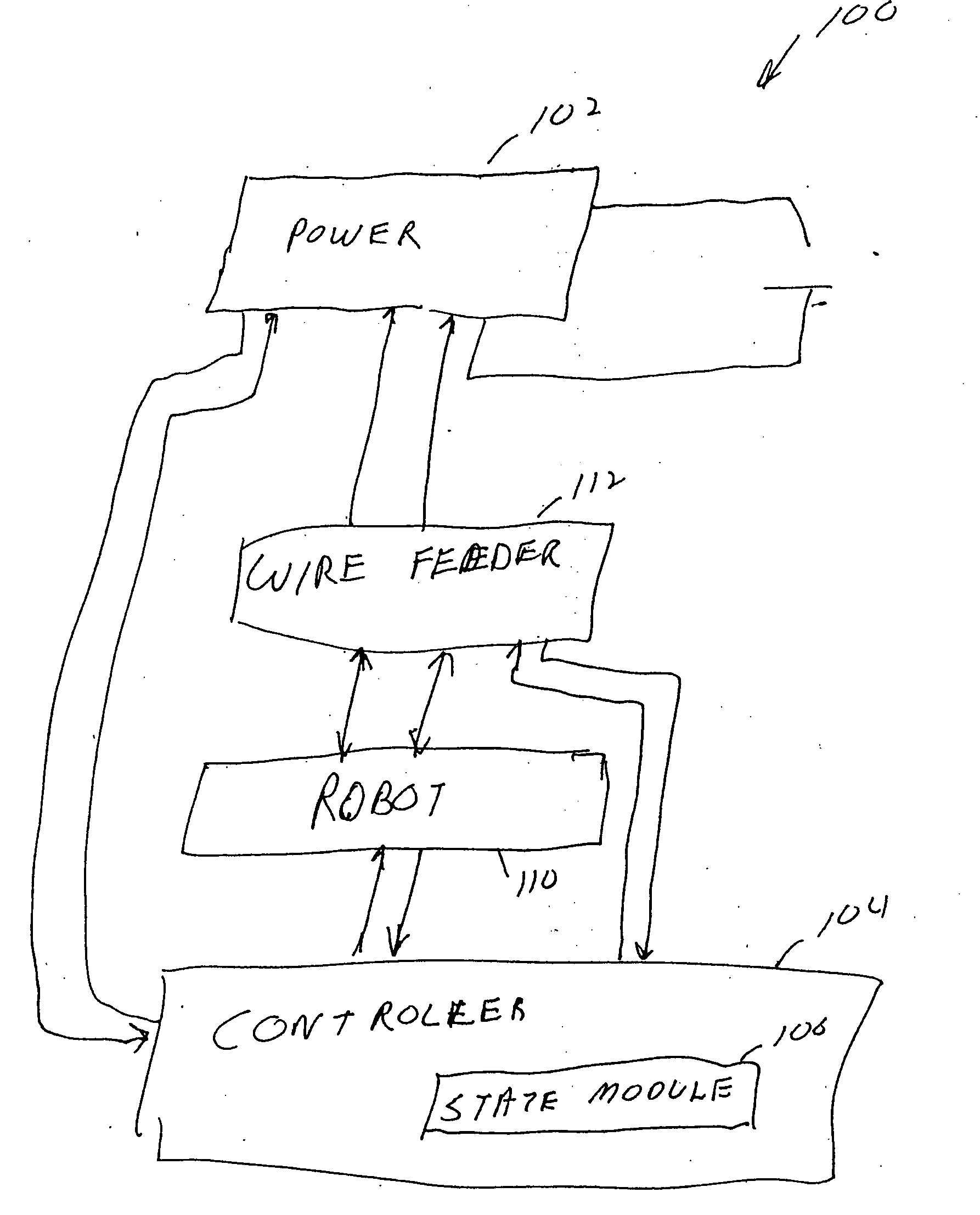
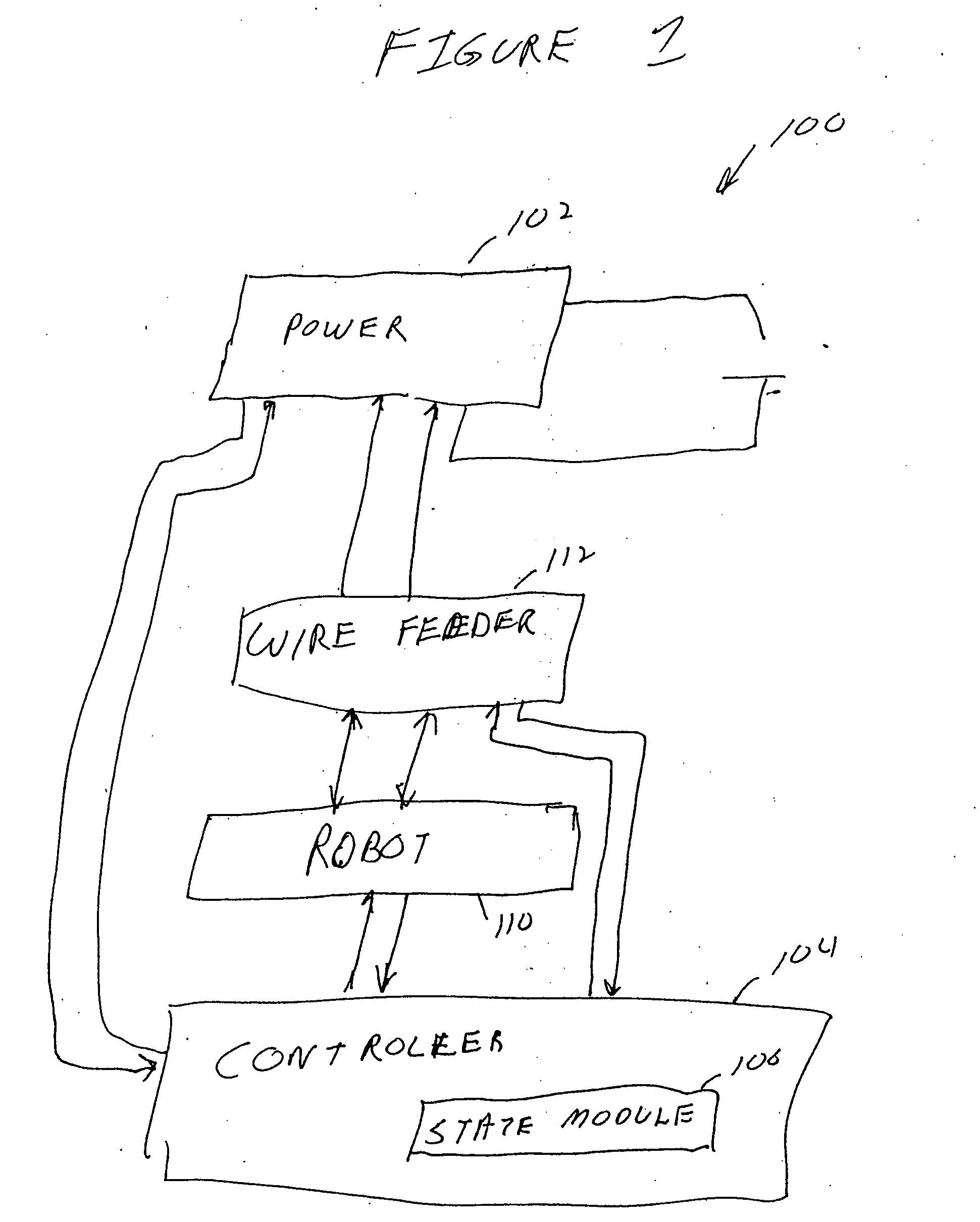
The invention is a system and method for controlling a welding-type power source using a state-based control scheme. The system includes a controller with a state-based control module that uses software instructions and a digital processor to determine the current state of the system and select the subsequent state based on the current state and one or more conditions. The system can also include a feedback circuit and operational welding peripherals such as a wire feeder or robot. The technical effects of the invention include improved efficiency and accuracy in welding processes, reduced downtime for maintenance, and improved safety compliance.

Problems solved by technology

While how to write such a program is well known, it can be very difficult to modify such a program.
Modification can, of course, cause unexpected consequences or require re-writing of entire sections.
Such changes may be extremely time consuming, requires the person doing the modification to understand the software language and understand the particular interaction of all the hard coded lines in the system.
Also, with each change, software bugs may be introduced and the program can require extensive trouble-shooting.
This requires increasingly sophisticated control software, which only exacerbates the difficulty in updating or modifying a welding program.
Each addition to the code can lengthen the code, and make subsequent changes even more difficult.

Method used


Image

  • Welding-type power supply with a state-based controller
  • Welding-type power supply with a state-based controller
  • Welding-type power supply with a state-based controller

Examples


Embodiment Construction

[0024] While the present invention will be illustrated with. reference to a particular system and controller it should be understood at the outset that the invention may also be implemented with other systems and controls, used in other applications, and used with other data.

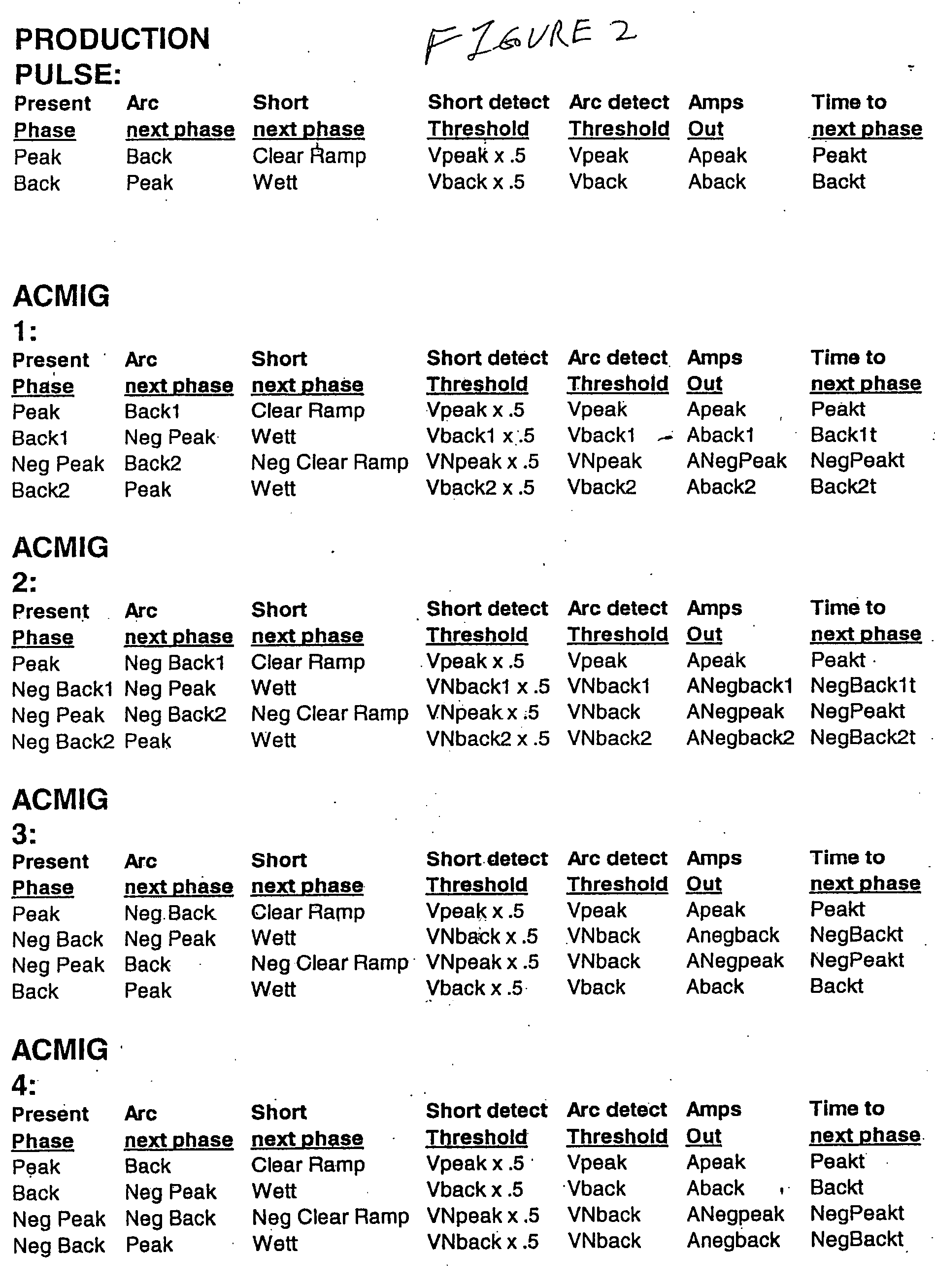
[0025] Generally, the invention relates to controlling a welding-type system using a state-based controller. The controller includes a state-based control module that has a state transition table stored in a spreadsheet database, preferably in non-volatile memory.

[0026] Controller, as used herein, includes digital and analog circuitry, discrete or integrated circuitry, microprocessors, DSPs, etc., and software, hardware and firmware, located on one or more boards, used to control a device such as a power supply or power source. State transition table, as used herein, includes a table showing subsequent states in view of the current state and the conditions that lead to the subsequent states. State-based contro...


PUM

PropertyMeasurementUnit
current stateaaaaaaaaaa
dimensionsaaaaaaaaaa
timeaaaaaaaaaa

Abstract

A method and apparatus for providing welding-type power includes a source of welding-type power and a controller. The controller is a state-based controller, and / or a deterministic control module, connected to the controller output. The state-based control module includes, in an embodiment, software instructions and a digital processor, and / or a state transition table stored in a spreadsheet data base. The controller is responsive to a feedback circuit. One or more welding peripherals, such as a wire feeder or robot, are connected to the controller. The current state may be represented by data in a first line of a spreadsheet and a state-ending event by a second, perpendicular, line of a spreadsheet. The subsequent state is determined by the intersection of the first and second lines in another embodiment.

Description

FIELD OF THE INVENTION [0001] The present invention relates generally to the art of welding-type power supplies. More specifically, it relates to the control of welding-type power supplies. BACKGROUND OF THE INVENTION [0002] Welding power supplies or systems are available for a wide variety of processes, and with a wide variety of sophistication. Welding-type power supply or system, as used herein, includes power supplies or systems that provide welding, cutting or heating power, and may include a controller, switches, etc. Traditionally, a good weld required an experienced welder, not only to properly execute the weld, but to properly select operating parameters (such. as output voltage, current, power, pulse width, wire feed speed, etc.) [0003] Now, robots are available that execute the weld. Also, operating parameters may be pre-determined and automatically implemented by a controller in the weding-type power supply. The automation is typically a software program that describes t...

Claims


Application Information

Patent Timeline
Patent Type & Authority Applications(United States)
IPC IPC(8): B23K9/10B23K9/095B23K9/12
CPCB23K9/0953B23K9/1062B23K9/124
Inventor HOLVERSON, TODDDAVIDSON, ROBERTUECKER, JAMES
Owner ILLINOIS TOOL WORKS INC
Learn More