Thermostatic mixing valves

a technology of mixing valves and valves, applied in multiple way valves, slide valves, instruments, etc., can solve the problems of increased manufacturing costs, vibration of valve shuttles generating noise, misalignment of valve shuttles, etc., and achieve enhanced response, enhanced response, and increased total flow rate through valves

Active Publication Date: 2006-06-15
KOHLER MIRA LTD
View PDF14 Cites 18 Cited by
  • Summary
  • Abstract
  • Description
  • Claims
  • Application Information

AI Technical Summary

Benefits of technology

[0026] In one arrangement, the diverter means is arranged such that a proportion of the hotter water is diverted away from the thermostat. By diverting a portion of the hotter water away from the thermostatic means, temperature deviations of the mixed water above the desired water temperature caused by changes in inlet water pressures are reduced. Also, where the diverted flow by-passes the chamber containing the thermostat, the total flow rate through the valve may be increased.
[0027] As will be appreciated, with the above arrangement, when the cold pressure increases (or the hot decreases), the thermostat sees a larger fall in temperature than it would normally see and this generates an enhanced response. Similarly, when the cold pressure decreases (or the hot increases), the thermostat sees a larger increase in temperature than it would normally see and this generates an enhanced response. Also, by diverting part of the hot flow away from the thermostat, the thermostat resides in water at a lower temperature than the actual outlet temperature when the main and diverted flows recombine, and this also generates an enhanced response.

Problems solved by technology

As a result, misalignment of the valve shuttle affects the flows of hot and cold water and this can have a significant effect on the operation of the valve.
For example, if the valve shuttle lifts off the hot seat unevenly, more of the hot water flows through one side of the valve and vice versa more of the cold water flows through the opposite side of the valve giving rise to asymmetric streams of hot and cold water producing incomplete mixing of the streams that affects the response of the thermal control system to correct any deviation in the outlet water temperature from the selected temperature.
It has been proposed to employ close fit sliding guides to keep the valve shuttle aligned with the seats but the sliding parts add complexity, increase manufacturing costs and are susceptible to corrosion and lime-scale causing friction.
Misalignment of the valve shuttle may also result in vibrations of the valve shuttle generating noise, especially under high pressure operating conditions.
Thus, the water velocity at the edge of the valve shuttle produces a low pressure region that tends to pull the valve shuttle towards its seat and any misalignment of the valve shuttle causes the pull to be uneven and this can start vibration of the shuttle valve against its seat in what we believe is a nutating motion generating noise.
Traditionally, the return spring is a helical coil spring of wire of circular cross-section and this may contribute to misalignment of the valve shuttle.
This problem persists even if the best quality helical wire springs are used.
Normally, higher hot water pressure results in increases in the temperature of the mixed water at the outlet and higher cold water pressure results in decreases in the temperature of mixed water at the outlet.
This is unacceptable for many applications, for example in healthcare installations, and currently the performance requirements for these applications are met by skewing the response of the valve to reduce the size of hot deviations which may give rise to a risk of scalding with a consequential increase in the size of cold deviations which although noticeable to the user present less risk.
As a result, skewing the response is usually done on a trial and error basis until a response is achieved that meets the standard.
This is inefficient and there is still a possibility that a valve could be used under conditions in which the cold water and hot water pressures are not equal resulting in hotter temperature deviations than intended.
Moreover, it may not always be possible to meet the performance requirements by skewing the response of the valve.

Method used


Image

  • Thermostatic mixing valves
  • Thermostatic mixing valves
  • Thermostatic mixing valves

Examples


Embodiment Construction

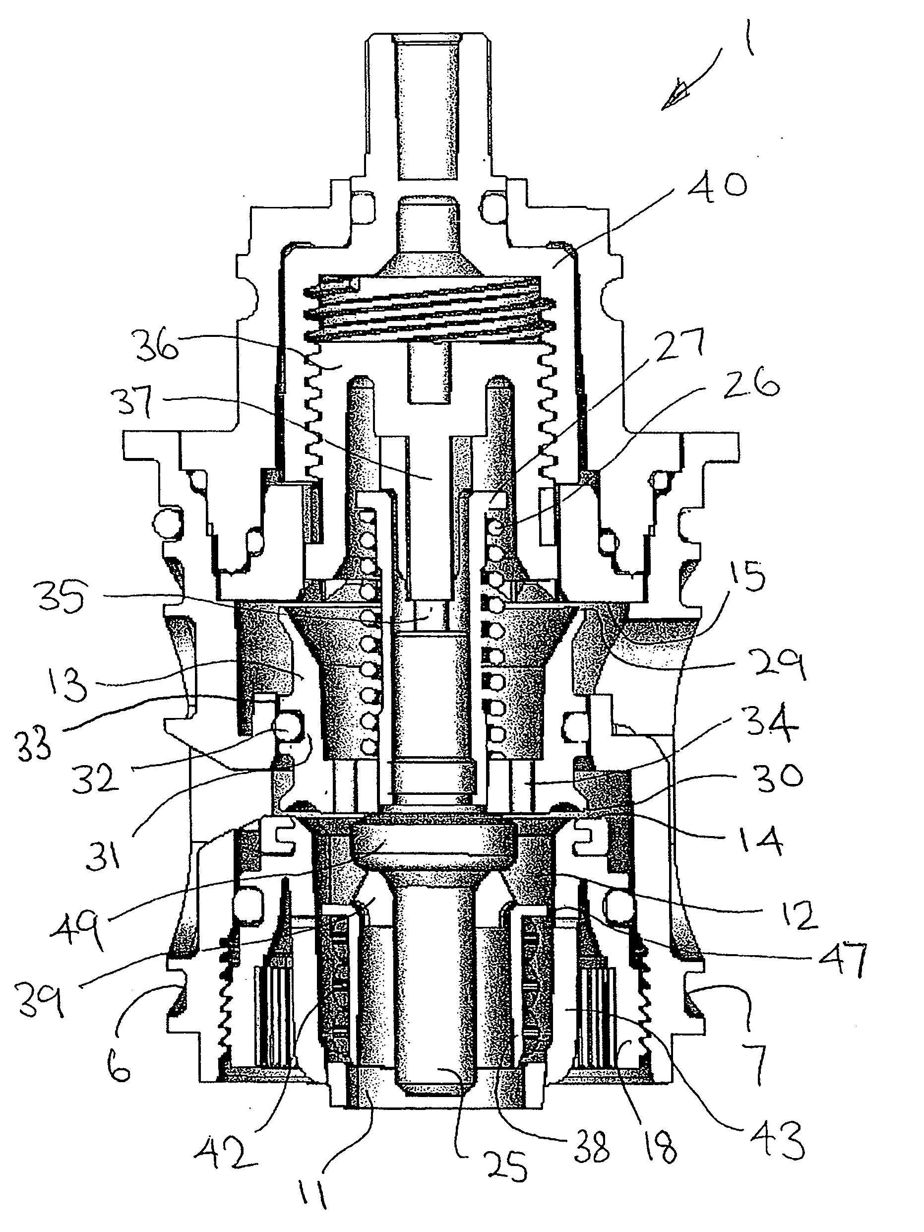
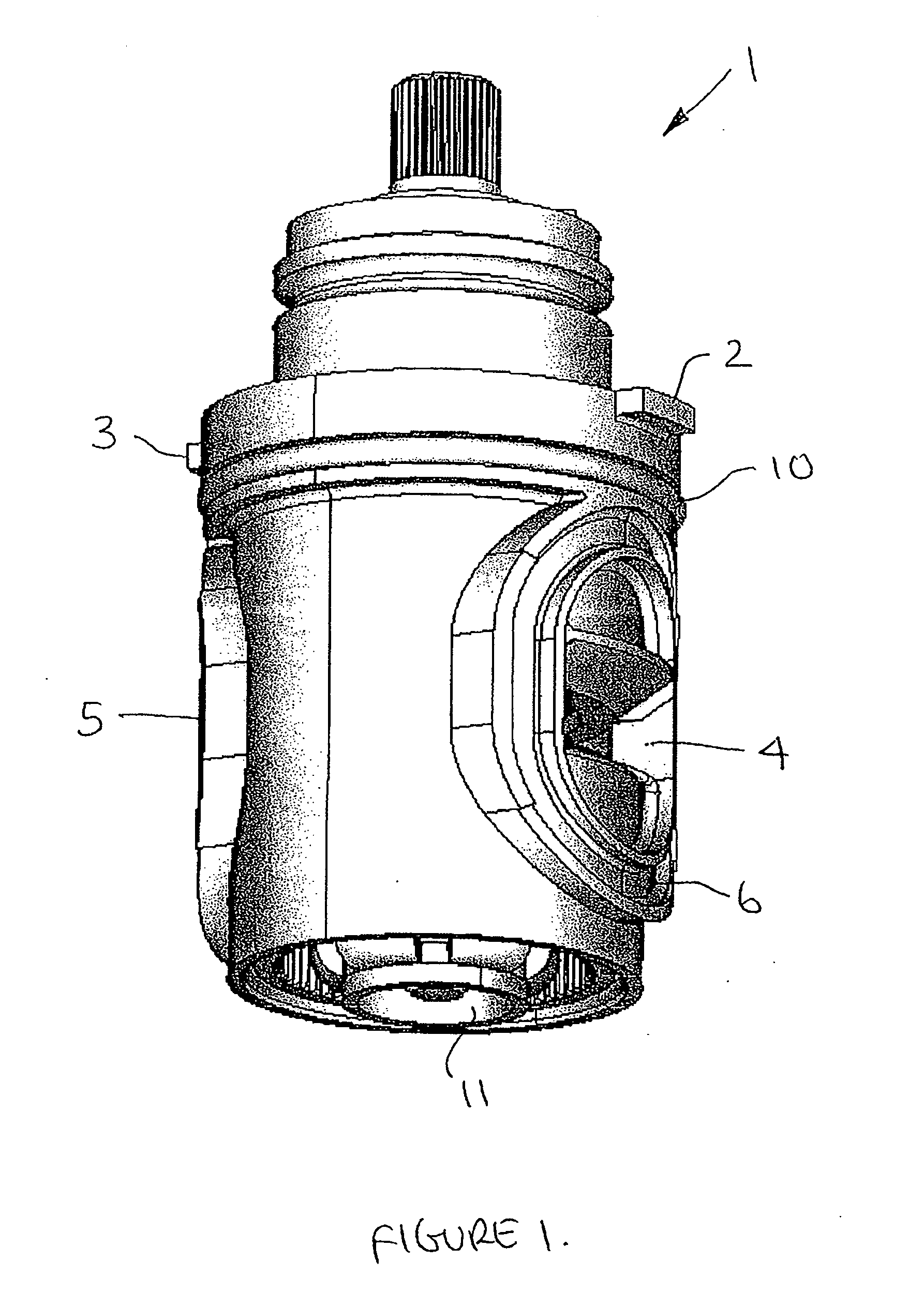
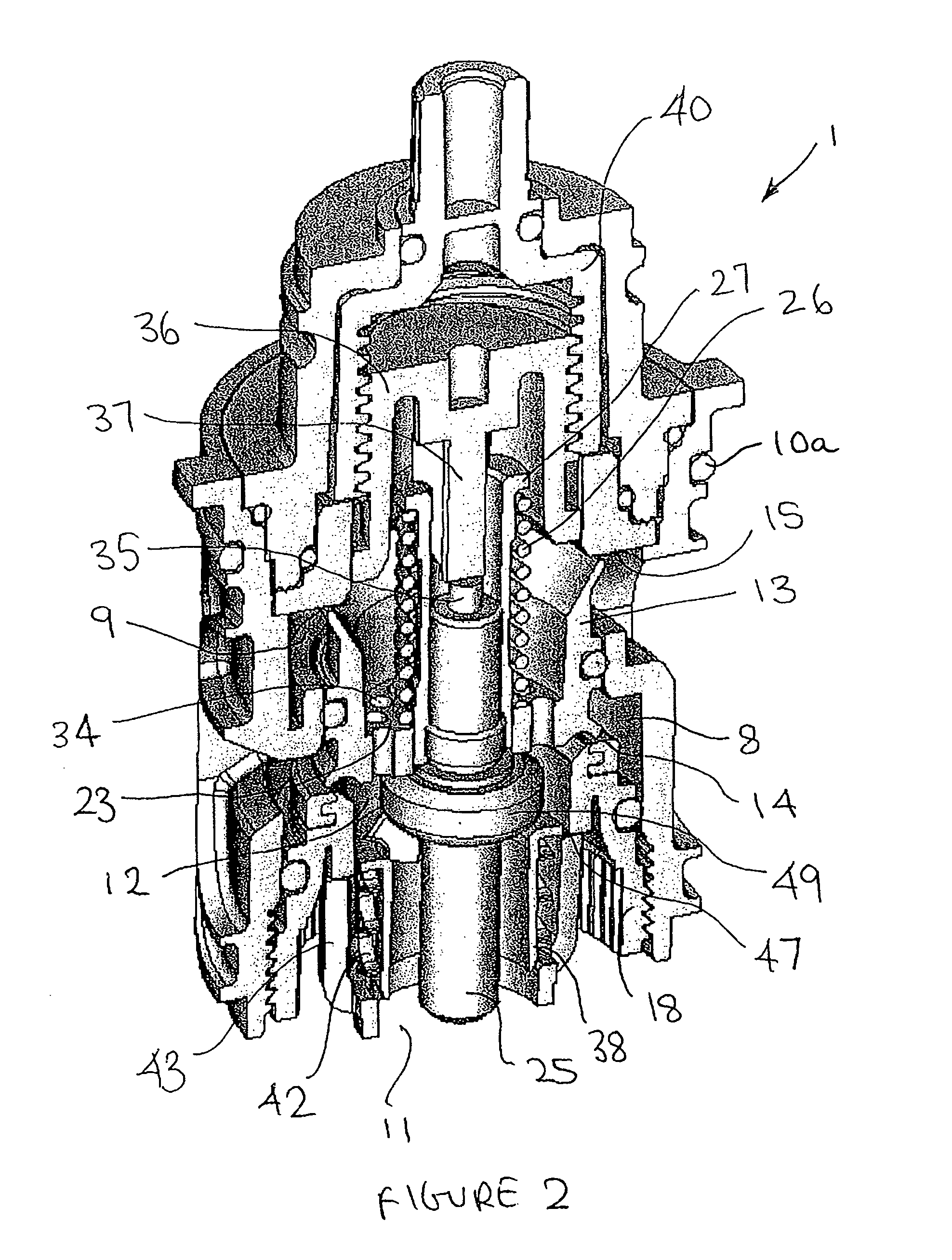
[0037] With reference to FIGS. 1 to 4, there is shown a thermostatic cartridge unit 1 of a mixing valve for a water supply installation such as a shower, bath or basin. The cartridge unit 1 is removably mounted in a body (not shown) of the mixing valve and has an annular groove 10 for an O-ring seal 10a (FIG. 2) to seal the cartridge unit 1 in the valve body.

[0038] The cartridge unit 1 has a pair of lugs 2,3 engageable with a pair of diametrically opposed notches in the valve body to prevent rotation of the cartridge unit 1 in the valve body and position the cartridge unit 1 to align inlets on the valve body for connection to supplies of hot and cold water respectively with a hot water inlet 4 and a cold water inlet 5 on the cartridge unit 1.

[0039] The inlets 4,5 are sealed relative to the opposed inlets in the valve body by O-rings (not shown) received in annular grooves 6,7 in the outer surface of cartridge unit 1 around the inlets 4,5. At a lower end of the cartridge unit 1 is ...


PUM


Abstract

A thermostatic mixing valve for hot and cold water has a valve member for controlling the relative proportions of hot and cold water admitted to a mixing chamber according to user selection of a desired water temperature and a thermostat responsive to the mixed water temperature to adjust the position of the valve member to maintain constant the selected water temperature. The valve member is biased by a return spring in the form of a wave spring having a plurality of turns with transverse waves configured such that adjacent turns sit peak to peak. The wave spring is strong in compression and weak in torsion allowing the ends of the spring to move laterally to accommodate any misalignment in the components of the valve.

Description

FIELD OF THE INVENTION [0001] This invention concerns improvements in or relating to mixing valves. The invention has particular, but not exclusive, application to thermostatic mixing valves for water supply installations such as showers, baths and basins. BACKGROUND OF THE INVENTION [0002] Thermostatic mixing valves commonly employ a valve shuttle movable between hot and cold seats to control the relative proportions of hot and cold water supplied to an outlet in accordance with user selection of the outlet water temperature and a thermal control system to adjust the position of the valve shuttle to compensate for changes in the temperature and / or pressure of one or both supplies tending to change the set temperature. The known valve shuttles typically have a very small stroke, for example movement of the valve shuttle from full cold to full hot is generally less than 1 mm and is typically only 0.6 mm. As a result, misalignment of the valve shuttle affects the flows of hot and cold...

Claims


Application Information

Patent Timeline
Patent Type & Authority Applications(United States)
IPC IPC(8): G05D23/185G05D23/02F16K3/26G05D23/13
CPCF16K3/265G05D23/1346F16K11/0445G05D23/134
Inventor SANSUM, NIGEL PAULHOPSON, RICHARD TIMOTHY
Owner KOHLER MIRA LTD
Why Eureka
Try Eureka