Control system for high pressure oil wells

Inactive Publication Date: 2006-06-15
REFRACTRON TECH CORP
View PDF15 Cites 14 Cited by
  • Summary
  • Abstract
  • Description
  • Claims
  • Application Information

AI Technical Summary

Benefits of technology

[0008] In accordance with this invention, there is provided a pressure reducing valve assembly for a high pressure oil well comprised of a hollow housing and a metering assembly disposed within such housing, such metering assembly comprising an entry liner having an entry bore, an exit liner having an exit bore, and a rotatable metering cam comprising at least one metering port that connec

Problems solved by technology

The adjustable device of Yancey, however, is not very durable, unduly restricts fluid flow, and often causes undesired turbulent fluid flow.
This device

Method used


Image

  • Control system for high pressure oil wells
  • Control system for high pressure oil wells
  • Control system for high pressure oil wells

Examples


Example

[0041] The present invention will be described in connection with a preferred embodiment, however, it will be understood that there is no intent to limit the invention to the embodiment described. On the contrary, the intent is to cover all alternatives, modifications, and equivalents as may be included within the spirit and scope of the invention as defined by the appended claims.

DESCRIPTION OF THE PREFERRED EMBODIMENTS

[0042] For a general understanding of the present invention, reference is made to the drawings. In the drawings, like reference numerals have been used throughout to designate identical elements.

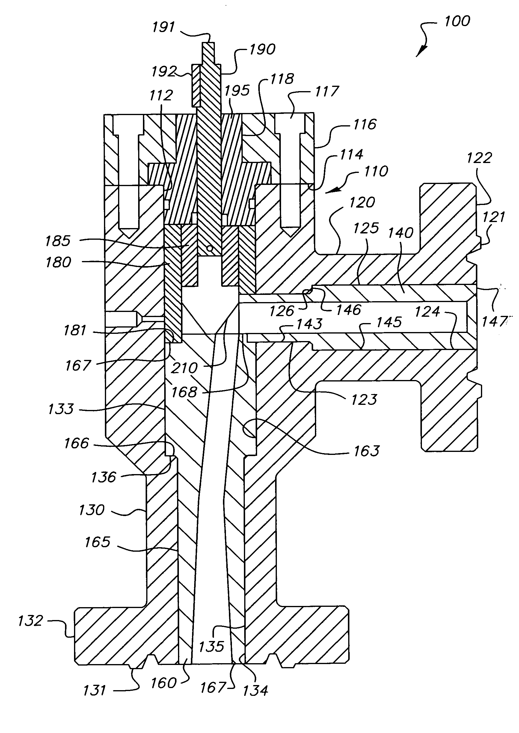
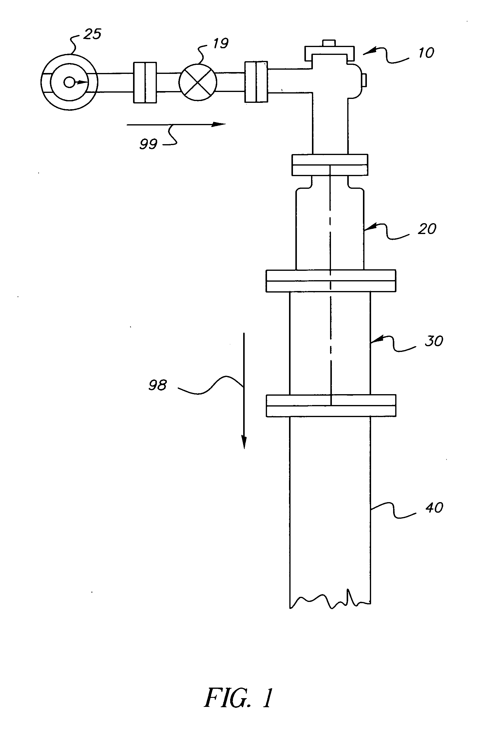
[0043]FIG. 1 of this patent application is similar to FIG. 1 of U.S. Pat. No. 6,367,546; and it illustrates a pressure reducing assembly for a high pressure well head. Referring to FIG. 1, and to the embodiment depicted therein, and also to such patent, it will be seen that, in the assembly 8 depicted, oil flow indicated by arrow 99 originating from the well (not shown) fl...


PUM


Abstract

A pressure reducing valve assembly for a high pressure oil well comprised of a hollow housing and a metering assembly disposed within such housing, such metering assembly comprising an entry liner having an entry bore, an exit liner having an exit bore, and a rotatable metering cam comprising at least one metering port that connects the entry bore to the exit bore. The metering port forms adjustable orifices with the entry bore and the exit bore, and effects the reduction of pressure within the metering assembly, thereby providing a variable choke of the fluid flow therein. The metering port is adjustable, and preferably replaceable with at least a second metering port by with a simple rotation of the metering cam.

Description

FIELD OF THE INVENTION [0001] A pressure reducer assembly for regulating high-pressure fluid flow, wherein the assembly is comprised of a rotatable adjustable choke. BACKGROUND OF THE INVENTION [0002] In April of 2002, U.S. Pat. No. 6,367,546 issued to the applicant of the instant case, Ibrahim M. Mentesh; the entire disclosure of this United States patent is hereby incorporated by reference into this specification. This patent described and claimed: “A pressure reducing device for a high pressure well comprising: an elongated, generally cylindrical body having an inlet end and an outlet end, said body being formed of a technical ceramic material selected from the group consisting of alumina, chromium oxide, titania, zirconia, partially stabilized zirconia, silicon nitride, silicon carbide, and combinations thereof; a flow channel formed in said body extending along a longitudinal, central axis of said body from the inlet end to the outlet end, said flow channel terminating in an ou...

Claims


Application Information

Patent Timeline
IPC IPC(8): F16K47/00
CPCF16K5/0407F16K5/0414F16K5/0421F16K5/045Y10T137/7036
Inventor MENTESH, IBRAHIM M.
Owner REFRACTRON TECH CORP
Why Eureka
Try Eureka