Energy storage device, module thereof and electric vehicle using the same

Inactive Publication Date: 2006-06-15
HITACHI LTD
View PDF16 Cites 67 Cited by
  • Summary
  • Abstract
  • Description
  • Claims
  • Application Information

AI Technical Summary

Benefits of technology

[0035] According to the present invention, a plurality of energy storage devices are connected to form an energy storage device module in which the plurality of energy storage devices are connected (e.g. in series) in compliance with the desired voltages. The voltage detecting units for detecting these individual voltages and the control circuits for controlling the charging and discharging currents flowing in the individual energy storage devices are installed, and the units for sending commands to these units are also installed. The communications between these units are set to be conducted by means of electric signals. At the time of charging, when the voltages of the individual energy storage devices, detected by the voltage detecting units are lower than the preset charging voltages, electric currents are made to flow into the energy storage devices to charge the devices. For the energy storage devices having reached the preset charging voltages, the electric signals from the units for sending commands make the charging currents not flow into the e

Problems solved by technology

Conventional lithium secondary batteries are poor in charge/discharge characteristics for large current, and have a problem that the input/output charact

Method used


Image

  • Energy storage device, module thereof and electric vehicle using the same
  • Energy storage device, module thereof and electric vehicle using the same
  • Energy storage device, module thereof and electric vehicle using the same

Examples


example 1

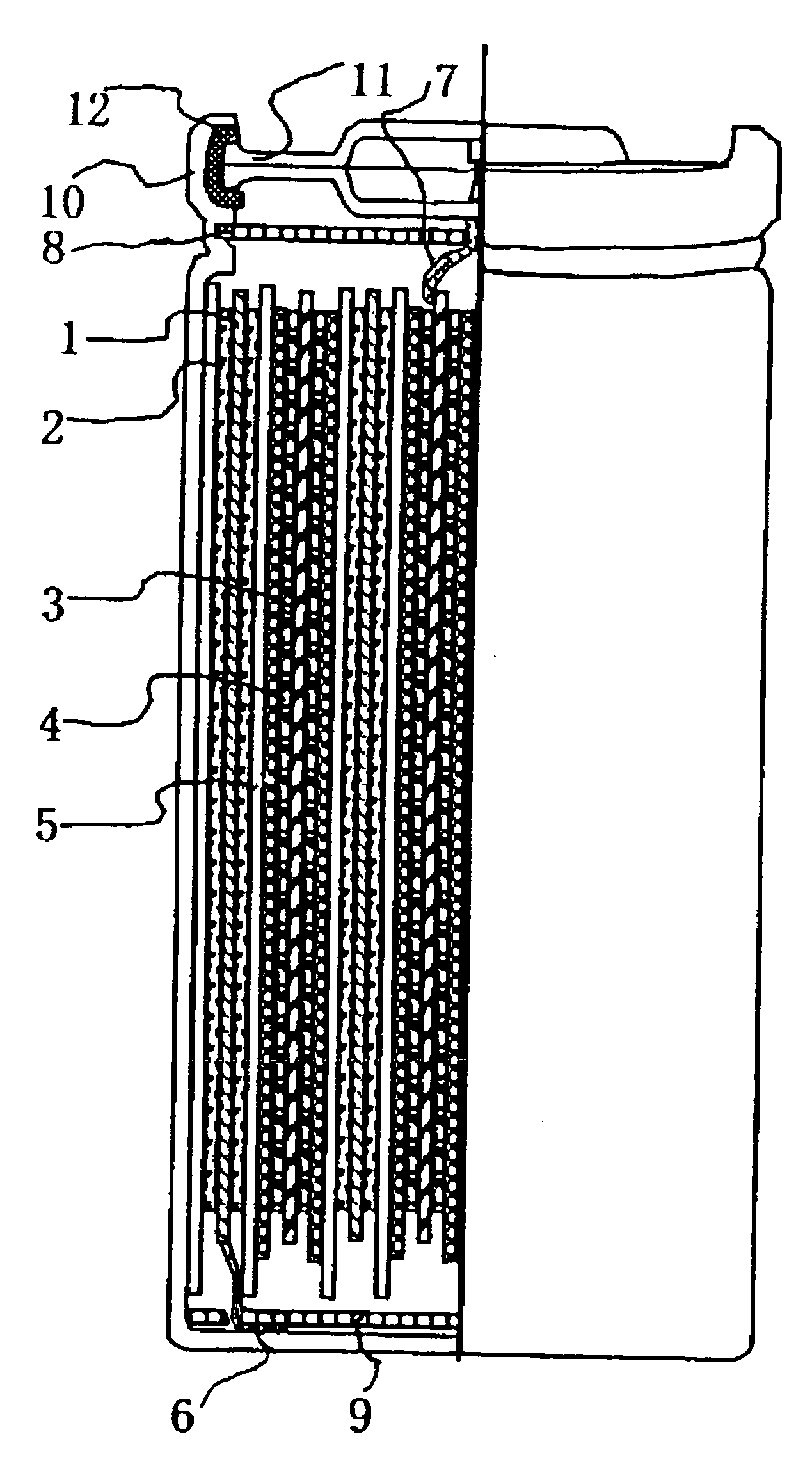
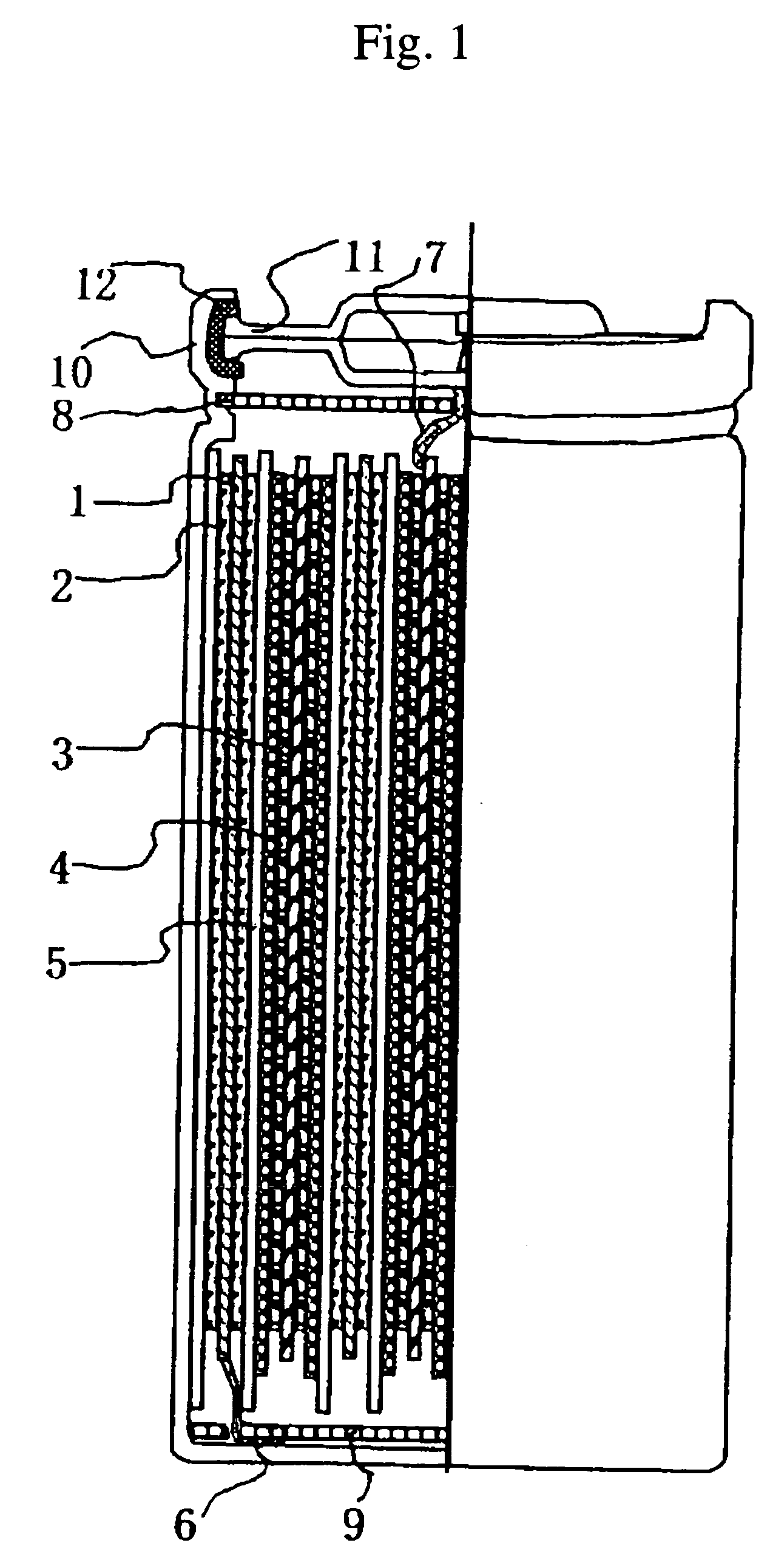
[0077]FIG. 1 is a partial sectional view of a cylindrical lithium secondary battery as an energy storage device showing an embodiment of the present invention. Positive electrode layers 2 formed as a positive electrode on both sides of a highly conductive current collector 1 were constituted with a region I belonging to a reaction, to occur through charge exchange, occluding / releasing lithium as a compound on the basis of a reaction to occur through charge exchange, and a region II belonging to a charge adsorbing / desorbing reaction to store electricity through adsorption / desorption based on the electric potential of the anion. The positive electrode composed of the current collector 1 and the positive electrode layers 2 was made to face a separator 5 having a large number of pores to hold an electrolytic solution and to allow mobile ions to permeate therethrough, and was further made to face a negative electrode through the intermediary of the separator 5.

[0078] A positive electrod...

example 2

[0090] The positive electrode was prepared as follows: as the active material in the region I where the reaction accompanied by charge exchange occurs in the positive electrode layer 2, LiNi1 / 3Mn1 / 3Co1 / 3O2 was used; as the conducting aid, a 4:1 by weight mixture of a graphite carbon having an average particle size of 3 μm and a specific surface area of 13 m2 / g and a carbon black having an average particle size of 0.04 μm and a specific surface area of 40 m2 / g was used; as a material forming the region II where the charge adsorbing / desorbing reaction occurs, an activated carbon having a relatively higher specific surface area of 2000 m2 / g was used; a positive electrode material paste was prepared with NMP as the solvent so as for the ratio between LiNi1 / 3Mn1 / 3Co1 / 3O2, the conducting aid, the activated carbon and the binder PVDF to be 77:5:10:8 in the solid content ratio by weight; and the both sides of a current collector 1 were coated with the paste, dried and pressed to prepare the...

example 3

[0091] The energy storage device of Example 3 was fabricated with the same electrode configuration as in Example 1 and with an electrolytic solution prepared by dissolving LiPF6 in a concentration of 1 M in a 3:3:1 by volume solvent mixture of EC, EMC and methyl acetate (MA) and by adding VC in a content of 2 wt %. The discharge capacity was 225 mAh, and the output power at −30° C. and at 3.65 V was 4.97 W, to be higher even by 26% than in Comparative Example 1.

EXAMPE 4

[0092] The energy storage device of Example 4 was fabricated with the same electrode configuration as in Example 1 and with an electrolytic solution prepared by dissolving LiPF6 in a concentration of 1 M in a 3:3:1 by volume solvent mixture of EC, EMC and methyl acetate (MA) and by adding VC in a content of 2 wt % and by further adding LiB[OCOCF3]4 in a content of 0.2 wt %. The discharge capacity was 222 mAh, and the output power at −30° C. and at 3.65 V was 5.15 W, to be higher even by 31% than in Comparative Examp...


PUM


Abstract

An object of the present invention is to provide an energy storage device excellent in input/output characteristics at low temperatures, a module thereof and a vehicle using the module. The present invention provides an energy storage device comprising: a positive electrode having a region where a reaction accompanied by charge exchange occurs; a negative electrode having a region where a reaction accompanied by charge exchange occurs; a separator electrically separating the positive and negative electrodes and allowing mobile ions to pass therethrough; an electrolytic solution having an aprotic nonaqueous solvent comprising the mobile ions; and a region in at least one of the positive and negative electrodes where a charge adsorbing/desorbing reaction occurs.

Description

FIELD OF THE INVENTION [0001] The present invention relates to a new energy storage device for storing / releasing electric energy, a module thereof and an electric vehicle using the module. BACKGROUND ART [0002] In these years, power supplies having higher input / output power than hitherto available are required as power supplies for electric vehicles, hybrid vehicles, electric tools or the like, and additionally, power supplies capable of rapidly charging / discharging and having high capacity are required. Particularly, power supplies having small temperature dependence and capable of maintaining input / output characteristics in a manner better than ever, even at low temperatures such as −20° C. or −30° C. are required. [0003] Such requirements as described above have hitherto been dealt with by making higher the performance of secondary batteries being mainly faradic in reaction mechanism such as lithium secondary batteries, nickel-hydrogen batteries, nickel-cadmium batteries and lead...

Claims


Application Information

Patent Timeline
IPC IPC(8): H01L27/148B60L50/16H01M4/02H01M4/13H01M4/38H01M4/40H01M4/505H01M4/525H01M4/58H01M10/05H01M10/052H01M10/0568H01M10/0569H01M10/0585H01M10/0587
CPCB60K6/28Y02T10/70B60K6/48B60L11/14B60L11/1853B60L11/1877B60L11/1879B60L2210/40B60L2240/12B60L2240/545B60L2240/547B60L2240/549B82Y30/00H01G9/035H01G9/22H01G11/06H01G11/10H01G11/46H01G11/60H01M4/505H01M4/525H01M10/052H01M10/0567H01M10/0569H01M2300/0042Y02E60/122Y02T10/6221Y02T10/7005Y02T10/7011Y02T10/7022Y02T10/705Y02T90/34Y02T10/7077Y02T10/7241Y02E60/13B60K6/32B60L50/16B60L58/18B60L50/66B60L50/64Y02E60/10Y02T10/62Y02T10/72Y02T10/7072Y02T90/40Y02P70/50
Inventor ARAI, JUICHIKUMASHIRO, YOSHIAKIYOSHIKAWA, MASANORIKOBAYASHI, MITURUYAMAKI, TAKAHIRO
Owner HITACHI LTD
Why Eureka
Try Eureka