
Endless track for high speed multi-terrain vehicles

Inactive Publication Date: 2006-06-15
SOUCY INT
View PDF49 Cites 14 Cited by
  • Summary
  • Abstract
  • Description
  • Claims
  • Application Information

AI Technical Summary

Benefits of technology

[0036] It is, thus, the objective of this invention to provide a workable solution to the problems by taking into account that such vehicle's undercarriage, to be truly useful, should be roadable, provide high traction and low ground compression, and minimally disturb the underlying terrain, as well as operate in the heavy duty working mode and provide a smooth ride for the operator in most soil conditions and topography from level land to steep inclinations while performing useful work without breaking the belts, losing drive capability between engaged wheels and belts, or disengaging the belts from the wheels.
[0038] It is another object of the present invention to replace metallic tracks by a reinforced rubber track which provides the advantages of metallic tracks (including good traction, support and adaptability to all types of terrain) while diminishing significantly the disadvantages (noise, damage to the ground surface, weight, short lifespan, maintenance and high costs).
[0045] While the invention is applicable to endless tracks for all track laying vehicles, its particular purpose is to increase the efficiency of heavy track laying all terrain vehicles such as military tanks that are specifically designed for normal speed travel over paved highways as well as for appropriate use over unpaved roads and uneven off road terrain.

Problems solved by technology

Problems encountered in actually reducing such an endless rubber track to practice include how to maintain adequate tension on such belt, how to drive such tracks and keeping the belt in lateral alignment with the wheels when the wheels are subject to large lateral loads.
Other problems are maintaining the structural integrity and providing long life for the belt, mid rollers, drive wheels, and idler wheels.
While smaller rubber tracked vehicles are commercially available, these do not carry adequate loads for military vehicles (including tanks), normal multi passenger or produce transports, and their drive wheels can easily become mired in heavy mud or snow.
As a result, the rubber tracks unavoidably get off the sprocket wheels or track rollers of the vehicle.
Various attempts have been made in order to prevent the dislodgement of the rubber tracks from the vehicle, but they have not met with success.
While the latter frictional resistive forces are a valuable attribute under wet or snowy conditions, they add undesirably to energy costs when driving the vehicle over flat, hard surfaces.
Solutions to the problems of actually implementing a heavy-duty vehicular rubber track drive system have proven elusive and scientific scaling techniques have not, to date, been successfully applied to light duty vehicles for purposes of developing a heavy duty rubber track system.
Thus, despite the long felt need for and the advantages thereof, a heavy duty application vehicle utilizing such rubber track system is commercially unavailable today.
However, these metallic tracks still present significant inconveniences in relation to wheeled vehicle.
The metallic track produces an excessively high level of noise.
This fact can cause a significant strategic disadvantage when used in association with military vehicles since the enemy can detect the presence of the military vehicle many miles away.
With respect to civilian vehicles equipped with such tracks or military vehicles used in peace keeping missions, the metallic tracks can cause significant damage to the ground surface whether it be paved or not.
Metallic tracks are very heavy.
Such a weight is both an inconvenience with respect to the mobility of the vehicles and with respect to their consumption of fuel.
Even metallic tracks provided with rubber pads wear out extremely rapidly such that the pads need to be replaced every 500 to 1000 miles on a military tank.
Metallic tracks also require a lot of maintenance.
Finally, the cost of manufacturing, maintenance and refurbishing are extremely high.
De-tracking is a phenomenon by which a track loses contact with the guiding system such that it will completely remove itself from the vehicle and thus cause it to stop.
If these drive lugs are allowed to skip over the teeth of the sprocket, damages to and premature wear of the track will occur.
The abrupt movements which result also cause significant discomfort to the passengers of the vehicle.
Tracks can also prematurely break down due to a number of other internal and external elements such as: breakage of reinforcing rods, tearing of the reinforcing fabric, cables and fibres and the abrasion, piercing, tearing and de-lamination of the rubber components.
The prior art solutions which are adapted for regular industrial and agricultural vehicles are inadequate when faced with the severity of the problems faced by military vehicles.
Indeed, the high weight of military vehicles combined to the high speeds and strong accelerations (both lateral and longitudinal) create high stresses in the track which considerably amplify the aforesaid problems.

Method used


Image

  • Endless track for high speed multi-terrain vehicles
  • Endless track for high speed multi-terrain vehicles
  • Endless track for high speed multi-terrain vehicles

Examples


Embodiment Construction

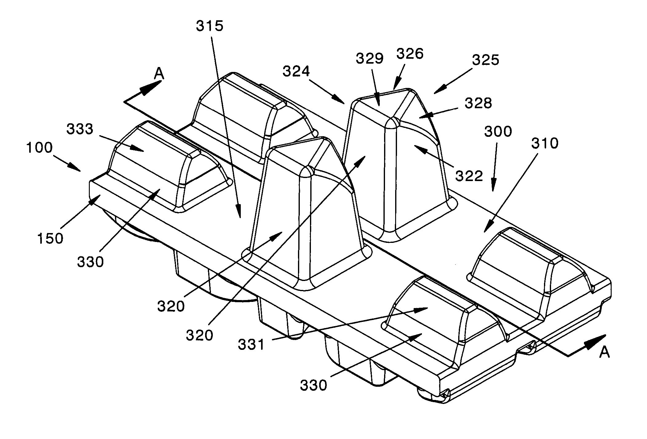
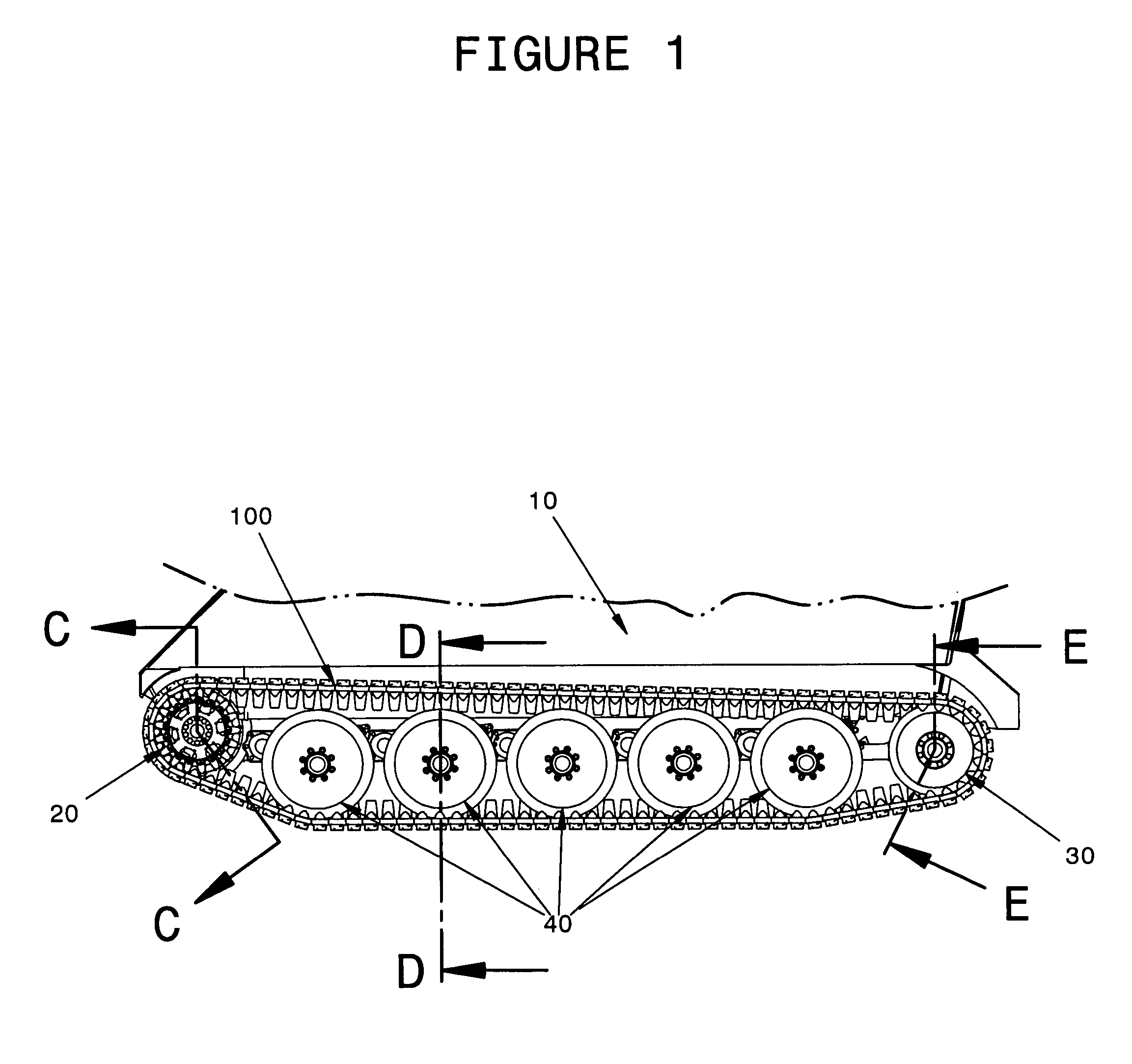
[0060]FIG. 1. shows a general side view of a rubber track system in accordance with this invention installed on a military vehicle 10. The track system comprises an endless reinforced rubber track 100, a sprocket drive 20, a tension wheel 30 and a plurality of guide wheels 40 which support the vehicle and guide the track 100. This system is coupled to appropriate drive means (not shown) through an appropriate suspension system (not shown). A similar system is disposed on the other side of the vehicle 10.

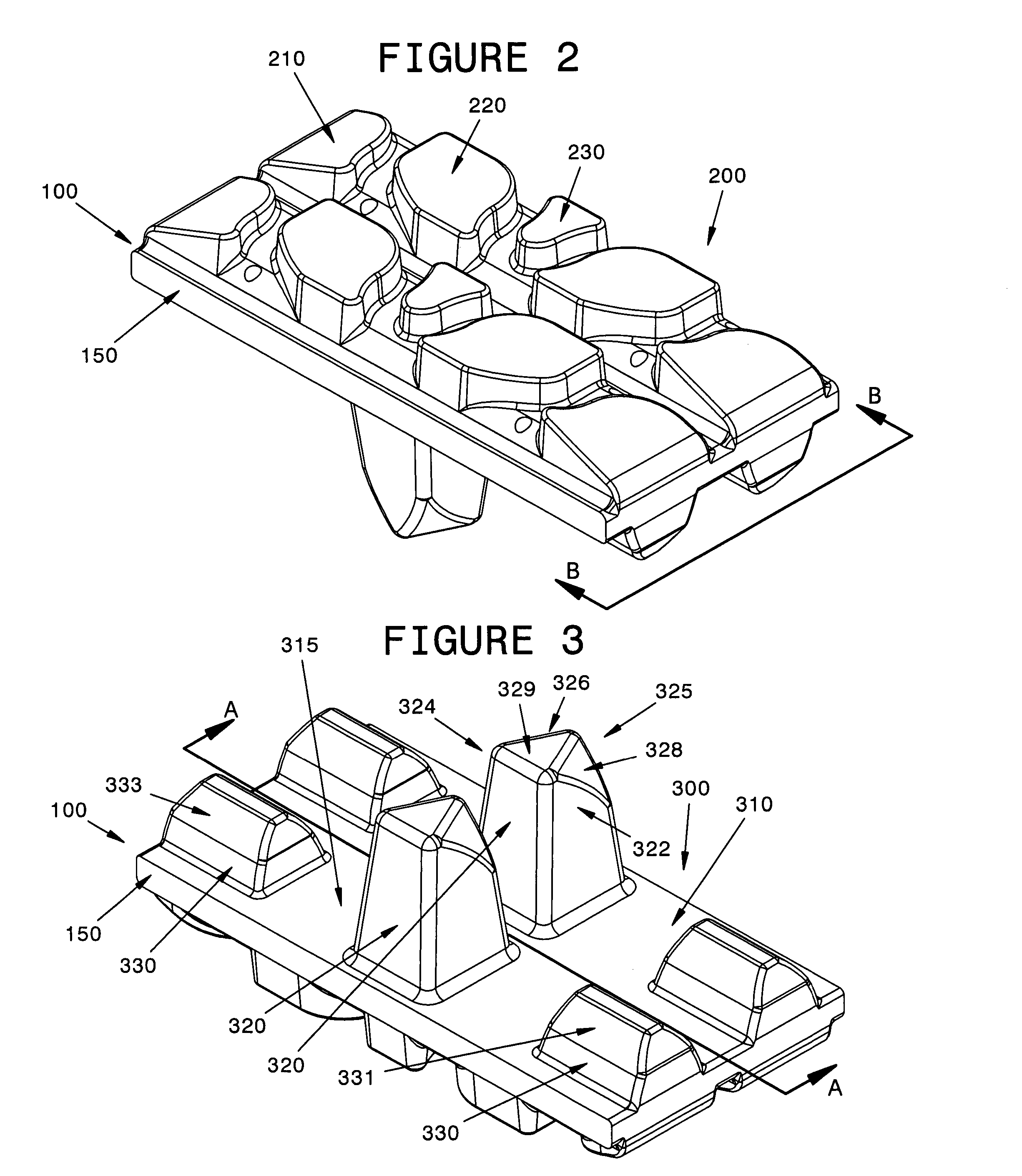
[0061] As shown in FIG. 2, a track 100 is typically built around a belt like carcass 150 made of reinforced rubber. As noted above, the term “rubber” relates to any appropriate elastic polymer. The belt 100 comprises an external surface 200 and an internal surface 300. As shown in FIG. 2, a plurality of traction lugs 210, 220 and 230 are disposed on the exterior surface 200. These traction lugs or tread interact with the surface on which the vehicle 10 is being displaced to ensure a...


PUM


Abstract

This invention relates to endless tracks and systems used to propel track laying vehicles [i.e., vehicles which use endless tracks rather than tires to contact the terrain over which they are driven, e.g., tractors, tanks, bulldozers, etc.] and, more particularly, to an improved rubber track design and system allowing the endless track to be driven more efficiently at highway speeds. The track is made from a polymer adapted to travel over a drive sprocket, a plurality of guide wheels and a tensioning wheel, the track having a first exterior ground engaging surface and a second interior drive sprocket engaging surface, the track comprising: a carcass portion in which reinforcements are embedded into the polymer; a plurality of tread lugs disposed on the first engaging surface; a plurality of drive lugs disposed on the second engaging surface and a plurality of guide horns disposed on the second engaging surface.

Description

RELATED APPLICATION DATA [0001] This present application is a Continuation-in-Part of the commonly assigned U.S. patent application Ser. No. 09 / 984,307, filed on Oct. 29, 2001 and entitled “Endless Track for High Speed Multi-Terrain Vehicles”.BACKGROUND OF THE INVENTION [0002] 1. Field of the Invention [0003] This invention relates to endless tracks used to propel track laying vehicles [i.e., vehicles which use endless tracks rather than tires to contact the terrain over which they are driven, e.g., tractors, tanks, bulldozers, etc.] and, more particularly, to an improved rubber track design allowing the endless track to be driven more efficiently at highway speeds. [0004] 2. General Discussion [0005] Numerous types of vehicles are frequently used in terrain in which it is difficult for pneumatic tires to operate. Both military vehicles, such as tanks and amphibious vehicles, and civilian vehicles, such as tractors and recreational vehicles, are sometime utilized on terrains which a...

Claims


Application Information

Patent Timeline
IPC IPC(8): B62D55/12
CPCB62D55/125B62D55/14B62D55/24
Inventor SOUCY, GILLESFAUCHER, CLAUDEDELAND, ANDREDELISLE, MARC
Owner SOUCY INT
Learn More