
Electrically operated product, circuit for allowing a backup battery to be physically connected without being electrically connected

a technology of electrical operation and circuit, applied in the field of electrical circuit, can solve the problems of circuit not solving, requires a relatively large amount of current,

Inactive Publication Date: 2006-06-15
OLSEN DONALD
View PDF8 Cites 5 Cited by
  • Summary
  • Abstract
  • Description
  • Claims
  • Application Information

AI Technical Summary

Benefits of technology

[0008] The purposes of this circuitry are firstly, to provide a means for a backup battery to be physically connected at all times to the aforementioned device, secondly, to provide a means for the backup battery to become electrically connected to the device when AC line voltage is first supplied, thirdly, to provide a means for the backup battery to remain electrically connected to the device as a secondary power source whenever AC line voltage is subsequently terminated such as during a power failure, and lastly, to consume a minimal amount of current while performing all of these functions. Devices incorporating this circuitry will have the capability of being shipped from the manufacturer or to a customer with a charged battery pre-connected physically, but not electrically, as previously described. A typical application for this circuitry would include devices which may be installed before AC power is available, such as in new construction, and would include such devices as emergency lighting or monitoring equipment such as temperature alarms, security systems, smoke detectors and the like. A significant advantage of this circuitry is that, in scenarios such as the one previously described regarding new construction, it would eliminate the need of having personnel return to a facility to physically connect the battery once AC power is available.
[0009] It is possible to perform the functionality for which this circuitry is intended by using a latching relay, but there are a number of significant advantages that this circuitry offers over a relay based configuration: firstly, the circuitry, which will be subsequently disclosed, is less expensive than utilizing a relay, secondly, this circuitry can be configured in less space than a relay would require, making it possible to easily have the circuitry added to the respective device or even built into the battery itself, and thirdly, this circuitry will consume an extremely small fraction of the current required by a relay configuration. This last advantage is of particular importance when a device utilizing this circuitry is actually operating off of the battery, such as during a power failure. At such times, the life of the battery is dependent on the amount of current that is being drawn by the circuitry that it is powering. The minimal amount of current that is drawn by this circuitry will help to prolong battery life when such power failures occur.

Problems solved by technology

However, such a relay configuration requires a relatively large amount of current drawn from the backup battery in order to connect the battery to the light or other circuit.
A problem may occur when an appliance or emergency light having a backup battery is first installed in a building, office, store or other premises under construction or renovation before AC power has been applied.
Such a circuit does not solve the problem of having the backup battery physically connected to the load without being electrically connected, as once a load is placed on the battery without AC line voltage being connected to the circuit, the battery will be awakened from its sleep mode and provide current to the emergency light or other circuit to which it is connected.

Method used


Image

  • Electrically operated product, circuit for allowing a backup battery to be physically connected without being electrically connected
  • Electrically operated product, circuit for allowing a backup battery to be physically connected without being electrically connected
  • Electrically operated product, circuit for allowing a backup battery to be physically connected without being electrically connected

Examples


Embodiment Construction

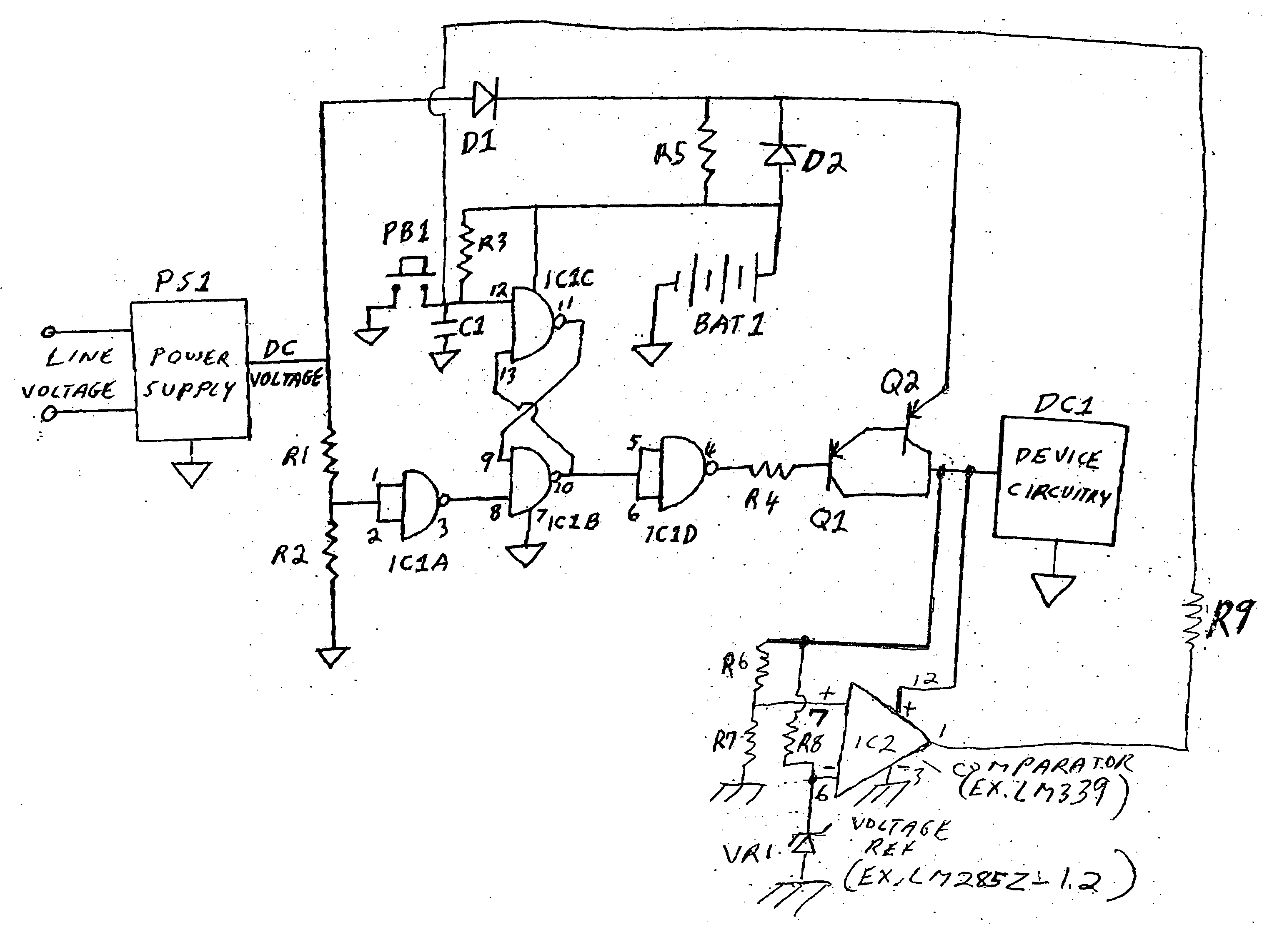
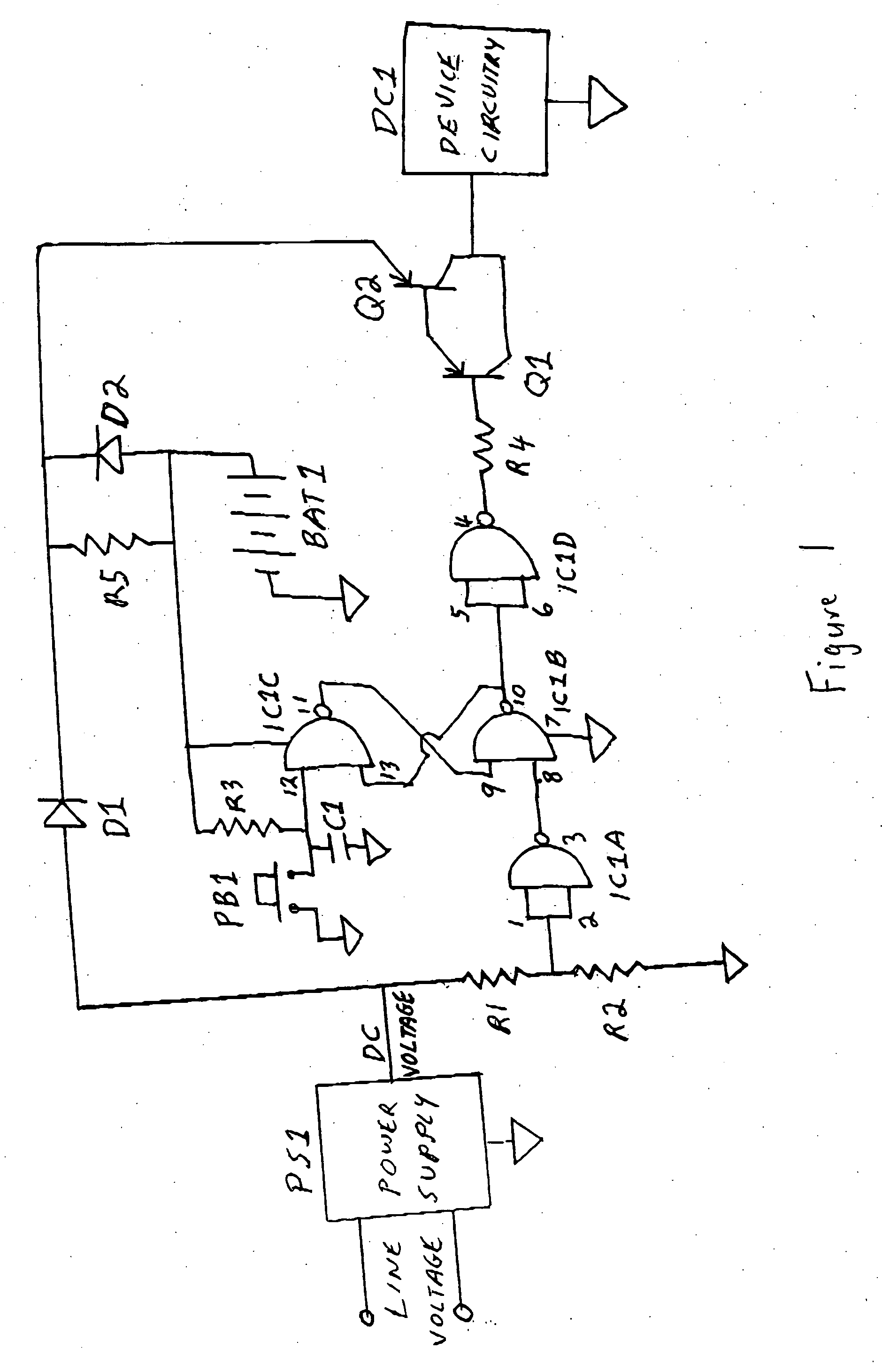
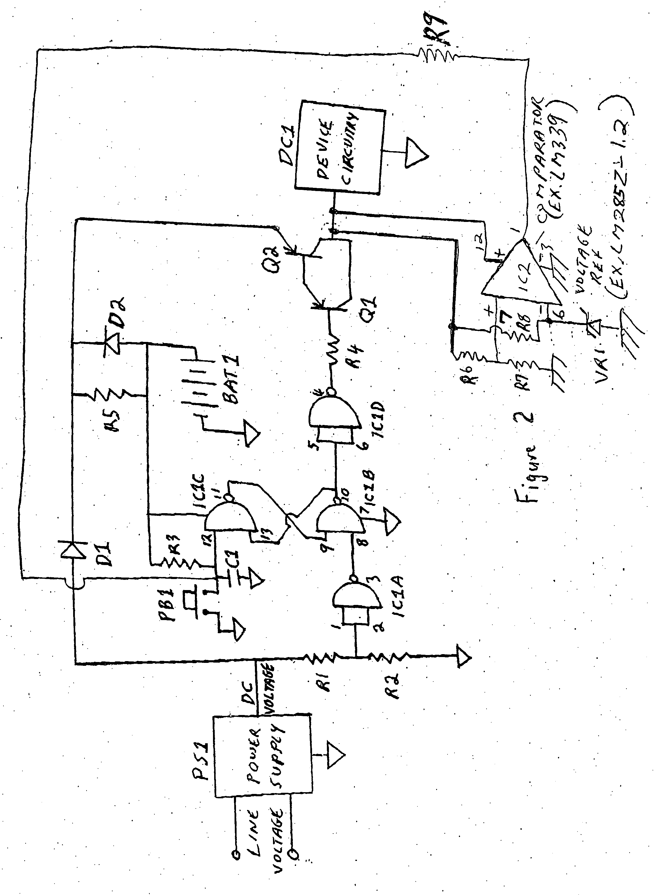
[0014] With reference to FIGS. 1 and 2, a description of the control circuit of the present invention will now follow.

[0015] PS1 is a block representation of a typical power supply, which is designed to take AC line voltage, normally 120VAC, change the line voltage to a lower voltage and then convert the lower voltage to DC voltage. This resultant lowered DC voltage is typically what is required to operate many electrical or electronic devices, and PS1 is the primary power source for device operation. BAT 1 is a battery, such as a 6 volt rechargeable battery, which serves as a secondary source of device operation when PS1 is not activated, such as during a power failure. D1 and D2 are diodes such as a 1N4001, and they are configured so that, while voltage supplied by PS1 and BAT 1 are joined as one power source for device operation, power from PS1 cannot feed back into BAT 1, and power from BAT1 cannot feed back into PS1. The joined cathode connection of D1 and D2 is then connected...


PUM


Abstract

A control circuit for selectively allowing a backup battery to be physically connected to a load without being electrically connected to the load includes a bistable multivibrator circuit, a power-to-load switching circuit connected to the multivibrator circuit, a delay circuit and a sleep state switching circuit. The multivibrator circuit is in a first sleep state when the backup battery is connected to the control circuit but no voltage is supplied to the control circuit from the power supply. Under these circumstances, the control circuit provides no power supply voltage or backup battery voltage to the load. The multivibrator circuit changes to a second state from the first state when a power supply voltage is provided to the control circuit after the multivibrator circuit is already in the first state. Then, the control circuit will provide either the power supply voltage or the backup battery voltage to the load. The multivibrator circuit remains in the second state unless it receives a signal from the sleep state switching circuit which places it back into the first sleep state.

Description

CROSS-REFERENCE TO RELATED APPLICATION [0001] This application is related to U.S. provisional patent application Ser. No. 60 / 636,404, filed on Dec. 15, 2004, and entitled “In an Electrically Operated Product, Circuit for Allowing a Backup Battery to be Physically Connected Without Being Electrically Connected”, the disclosure of which is incorporated herein by reference. This application claims the benefit of priority under 35 U.S.C. 119 to the aforementioned related provisional application.BACKGROUND OF THE INVENTION [0002] 1. Field of the Invention [0003] The present invention relates to an electronic circuit, designed for utilization in electrically operated devices which normally operate using standard AC line voltage as a power source, and which said devices also incorporate a backup battery as a secondary power source when AC line voltage is not available, such as during a power failure. [0004] 2. Description of the Prior Art [0005] A number of circuits, such as emergency ligh...

Claims


Application Information

Patent Timeline
IPC IPC(8): H02J9/00
CPCH02J9/061
Inventor OLSEN, DONALD
Owner OLSEN DONALD
Learn More