
Distributed sensor and control networking interface

Inactive Publication Date: 2006-06-15
FOARD GEYSEN
View PDF1 Cites 8 Cited by
  • Summary
  • Abstract
  • Description
  • Claims
  • Application Information

AI Technical Summary

Benefits of technology

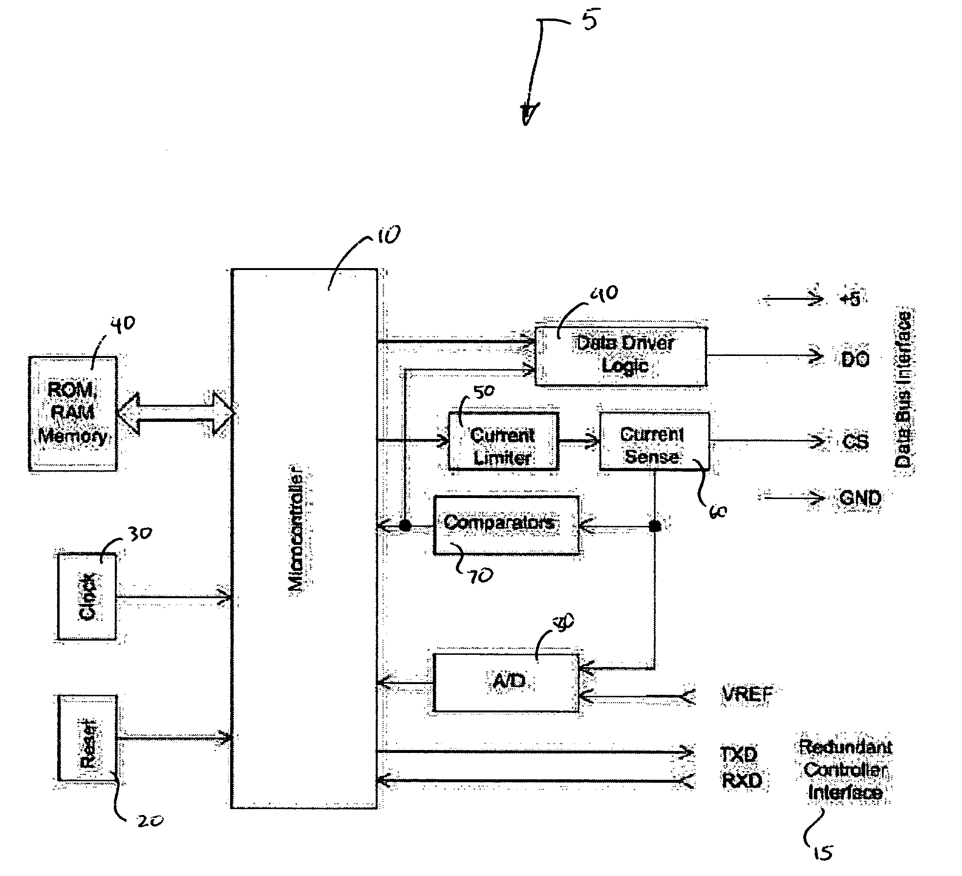
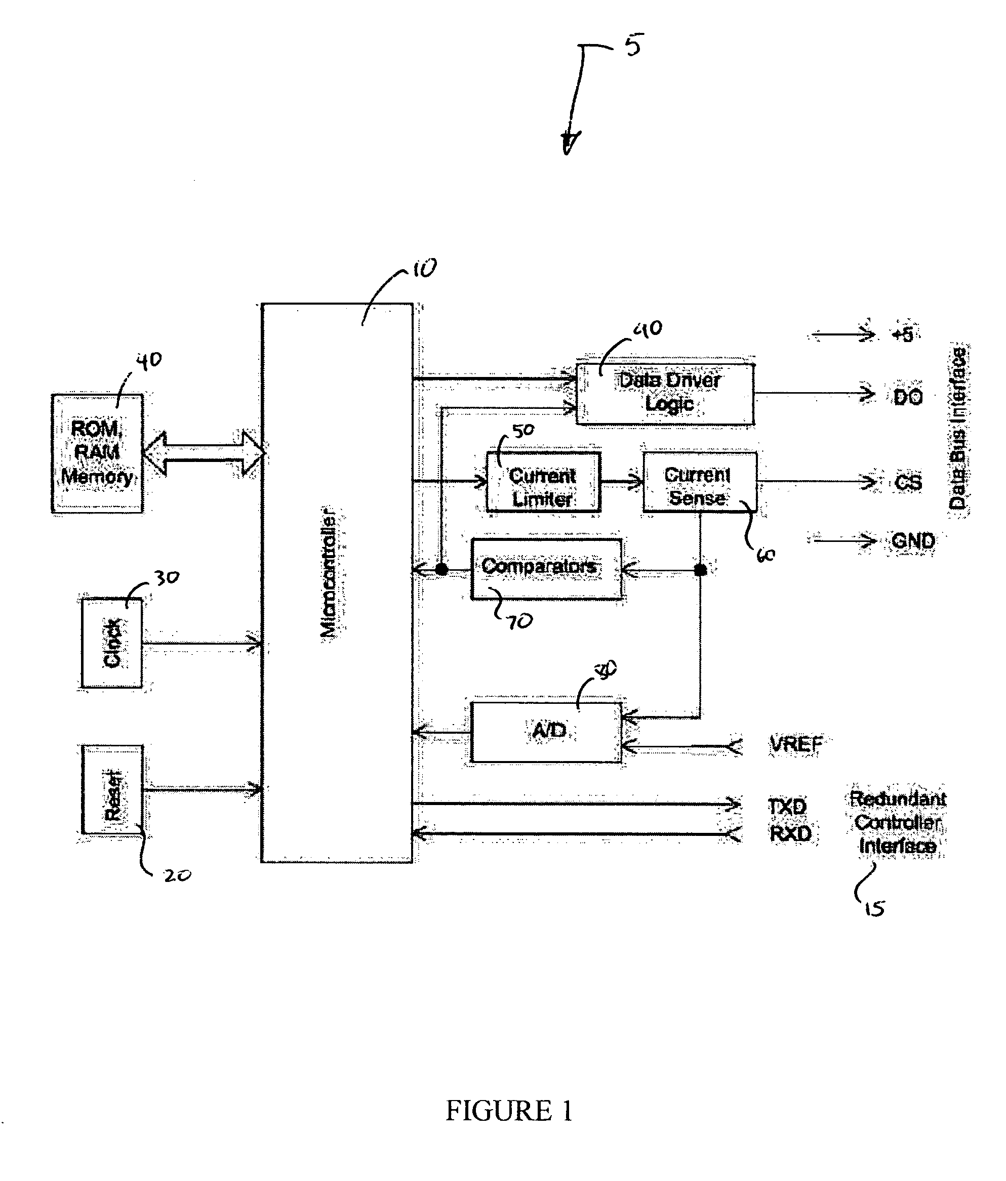
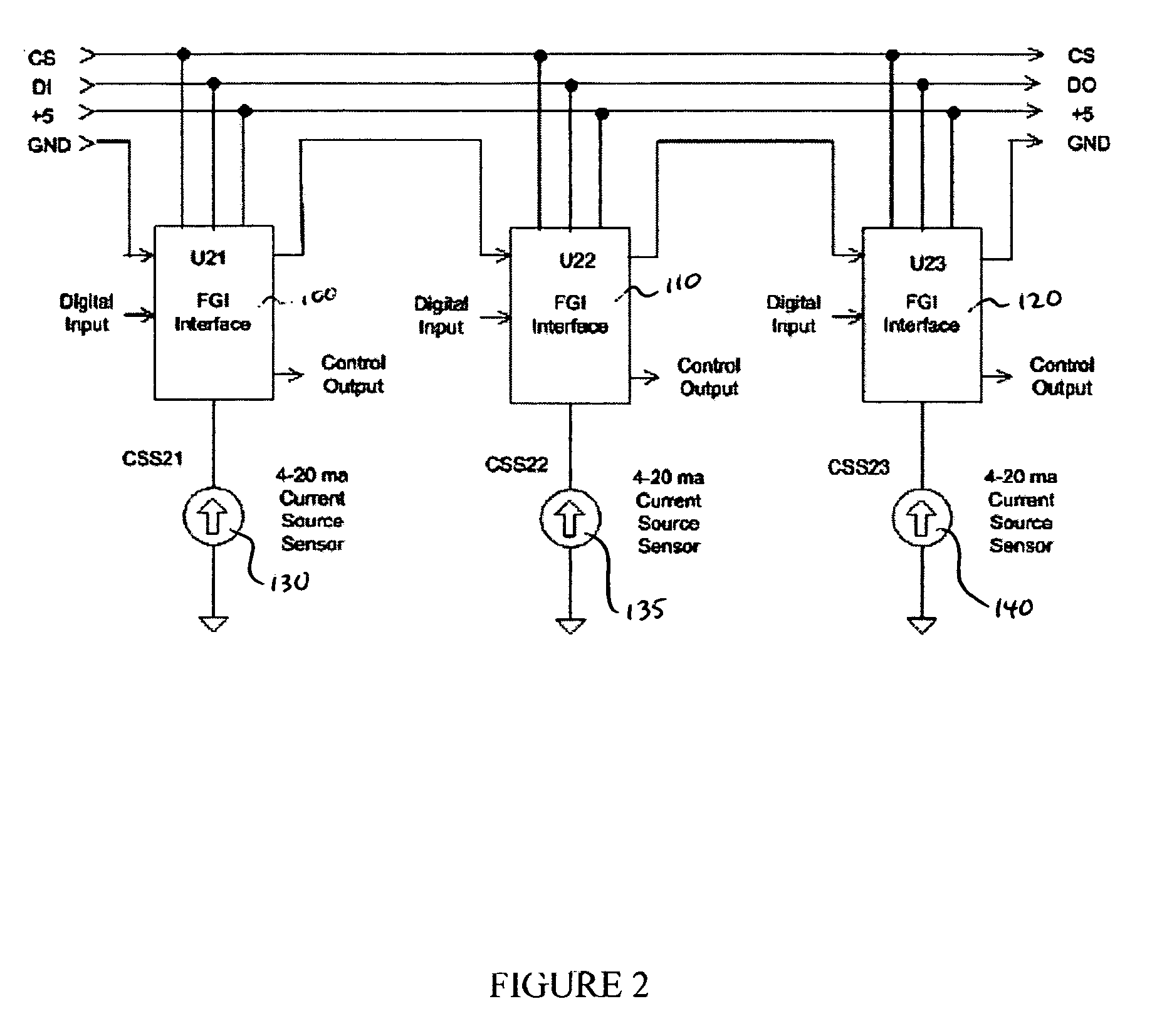
[0004] The present invention adds significant functional enhancements to existing switching systems. Some, but not all, of these enhancements include controlling multi-level system and device reset conditions; automatically identifying device types and unit identification numbers for devices attached to a switching system, providing a functionality similar to “plug and play” type operation; setting or programming the device type and / or unit identification numbers for a device via the switching system communications bus; adding branching to the wiring configuration or topology of the switching system; providing multi-line input and output interfaces to a device in the switching system, and means for efficiently notifying a system controller of input state changes; communicating via switching system devices to interconnected circuits or devices employing other interface protocols, such as RS-232, RS-422, RS-423, RS-485, J1708, SPI, Microwire, I2C, and the Dallas 1-Wire system; directly interfacing the switching system interface with complex interface devices, such as LCD / VFD / OLED display interfaces; auto-scanning devices, such as keyboards and optical encoders to improve system response, and in some cases reduce device power requirements; directly programming microprocessors and microcontrollers in devices attached to the switching system, without cooperating software executing in the attached devices; and implementing a mixed mode switching system, supporting intermixed master / slave communications between controllers and devices, and supporting peer-to-peer communications between devices as well as between controllers and devices.

Problems solved by technology

In many cases, a tradeoff exists between wiring complexity and interface electronics complexity, with many networking technology implementations requiring microprocessor level complexity at each device.

Method used


Image

  • Distributed sensor and control networking interface
  • Distributed sensor and control networking interface
  • Distributed sensor and control networking interface

Examples


Embodiment Construction

[0017] There are many possible implementations of the basic switching system design. In some implementations, additional functionality may be achieved by providing additional state control information from a controller, in addition to a state condition provided to a device by an interconnected device.

[0018] In one such implementation, a controller provides a state on the leading edge of a control clocking signal, while the state of the interconnected device is provided on the trailing edge of the clocking signal when device selection state is to be changed. In such a system, the state from the controller during the leading edge of the clocking signal may specify whether a selection state or whether a reset operation occurs. Multiple levels of reset conditions may be achieved by counting the number of reset operations that have been received since the occurrence of the latest selection state operation. For example, a single reset operation sequence might be used to reset the current...


PUM

PropertyMeasurementUnit
Timeaaaaaaaaaa
Phaseaaaaaaaaaa

Abstract

The invention provides systems and methods for a distributed sensor and control networking interface.

Description

FIELD OF THE INVENTION [0001] The present invention relates generally to switching systems and methods. More particularly, the present invention provides a distributed sensor and control networking interface. BACKGROUND OF THE INVENTION [0002] Distributed sensor and control networks can be implemented based upon any number of different communication interface technologies. In many cases, a tradeoff exists between wiring complexity and interface electronics complexity, with many networking technology implementations requiring microprocessor level complexity at each device. [0003] One technology for communicating with a plurality of remote devices, featuring low complexity in both wiring and device implementation requirements, relies on a switching system where the state of each device is dependent upon the state of an interconnected device, as described in U.S. Pat. No. 5,469,000; Australian Patent No. 643,231; Canadian Patent No. 2,065,373; and European Patent Application No. 048758...

Claims


Application Information

Patent Timeline
IPC IPC(8): B23K11/24
CPCG06F1/3209G06F1/324Y02B60/1217Y02D10/00
Inventor FOARD, WILLIAM WILLIAMS
Owner FOARD GEYSEN
Learn More