
Duty cycle controller for high power factor battery charger

a technology of duty cycle controller and battery charger, which is applied in the direction of electric variable regulation, process and machine control, instruments, etc., can solve the problems of mosfet damage, battery charger users have no way of limiting ac line current, and build up

Active Publication Date: 2006-06-15
XANTREX LLC
View PDF25 Cites 71 Cited by
  • Summary
  • Abstract
  • Description
  • Claims
  • Application Information

AI Technical Summary

Benefits of technology

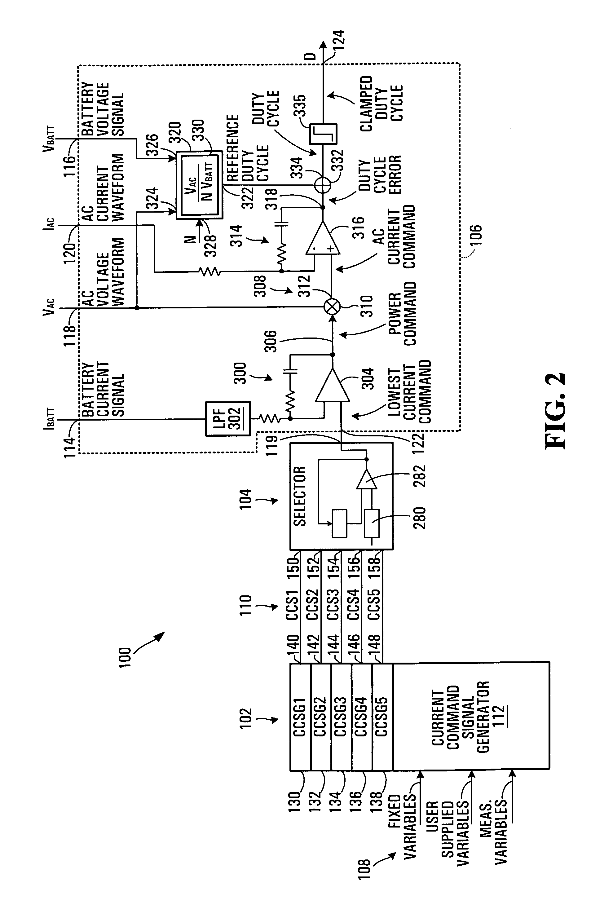
[0115] In general the invention permits various sets of operating conditions of the charger to be used to establish a plurality of current command signals, the lowest of which is used to finally control the duty cycle of switches in the charger to prevent inappropriate conditions being experienced or caused by the charger.

Problems solved by technology

This heat can build up, if not properly dissipated, to a point where the MOSFETs can become damaged.
Typically, users of battery chargers have no way of limiting AC line current supplied to a battery charger as most chargers provide few controls and many simply have only a line plug for controlling the operation of the charger.
However, the above-described methodology only works if the circuit topology permits control of the current.
When the instantaneous AC input voltage divided by the transformer turns ratio exceeds the battery voltage the battery current is essentially uncontrolled and limited only by parasitic impedances in the AC source, the charger, the battery, and the associated wiring.
However, in this situation only very coarse control of battery current is possible and such control may be unpredictable due to battery and AC source characteristics.

Method used


Image

  • Duty cycle controller for high power factor battery charger
  • Duty cycle controller for high power factor battery charger
  • Duty cycle controller for high power factor battery charger

Examples


Embodiment Construction

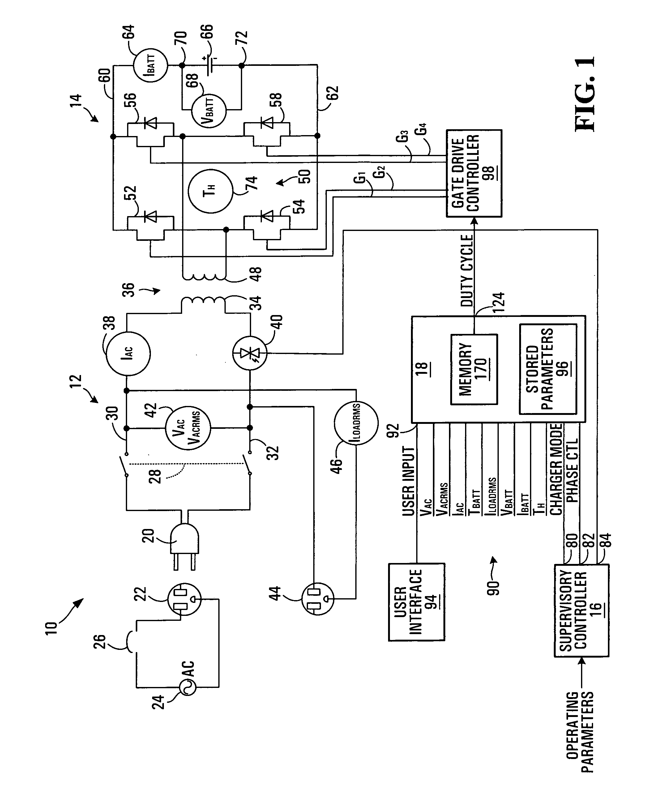
[0130] Referring to FIG. 1, a battery charger according to a first embodiment of the invention is shown generally at 10. The battery charger 10 includes a high voltage circuit shown generally at 12, a low voltage circuit shown generally at 14, a supervisory controller 16, a duty cycle controller 18, a user interface 94 and a gate drive controller 98.

[0131] The high voltage circuit 12 includes an AC plug 20 for receiving power from a receptacle 22 connected to an AC power source 24 through a breaker 26. The breaker 26 may be rated for 15 Amps, for example. The high voltage circuit 12 further includes an on / off switch 28 and line and neutral input terminals 30 and 32, respectively. The line and neutral input terminals 30 and 32 are connected to a high voltage winding 34 of a transformer 36 coupling the high and low voltage circuits 12 and 14 together. The input line terminal 30 is connected to the high voltage winding 34 of the transformer through a current sensor 38 or a plurality o...


PUM


Abstract

A duty cycle controller apparatus for producing a duty cycle signal for controlling switching of switches of a battery charger having an AC input for receiving power and an output for supplying power to charge a battery in response to switching of the switches, while maintaining a high power factor at the AC input. The duty cycle controller apparatus includes a current command signal generator having a plurality of signal inputs for receiving a plurality of signals representing a plurality of operating conditions of the charger, a plurality of current command outputs and a processor operably configured to generate a plurality of current command signals at the current command outputs in response to respective sets of operating conditions.

Description

BACKGROUND OF THE INVENTION [0001] 1. Field of Invention [0002] This invention relates to battery chargers and more particularly to generation of a duty cycle signal for use in controlling switches in a battery charger to control current flow to a battery being charged by the battery charger while maintaining a high power factor at an AC input of the battery charger. [0003] 2. Description of Related Art [0004] In conventional battery chargers, AC line voltage is stepped down by a transformer to produce a low voltage AC source which is connected to a switching array including Metal Oxide Semiconductor Field Effect Transistors (MOSFETs) for example, to provide a desired amount of current to a battery to be charged. MOSFETs have some “on” resistance which causes heat to be generated in the MOSFETs due to current flow through semiconductor junctions thereof. This heat can build up, if not properly dissipated, to a point where the MOSFETs can become damaged. Heat however, can be controll...

Claims


Application Information

Patent Timeline
Patent Type & Authority Applications(United States)
IPC IPC(8): H02J7/00
CPCH02J7/022Y02B40/90Y02B70/126H02M1/4233H02J7/02H02J2207/20Y02B40/00Y02B70/10
Inventor UNGER, THOMAS MICHAEL
Owner XANTREX LLC
Learn More