Multi-lens imaging systems and methods

a multi-lens imaging and imaging system technology, applied in the field of multi-lens imaging systems and methods, can solve the problems of poor color imaging, limited image resolution, and several handicaps of single-lens cameras

Active Publication Date: 2006-06-15
APTINA IMAGING CORP
View PDF15 Cites 259 Cited by
  • Summary
  • Abstract
  • Description
  • Claims
  • Application Information

AI Technical Summary

Benefits of technology

[0006] In accordance with the invention, imaging systems generally incorporate multiple lenses that are individually configured to receive visible light from an object to be imaged, and to direct this light upon a corresponding sensor array. Luminance information is then derived from signals generated in one or more of the sensor arrays.

Problems solved by technology

The single-lens camera suffers from several handicaps.
Some examples of such handicaps are: limited image resolution, poor color imaging, and improper luminance imaging.
Typically, image resolution limitations are a result of using a single sensor array containing a limited number of sensor elements.
Poor color imaging is generally a result of limited spectral bandwidth in the sensor elements of a sensor array.
Unfortunately, this technique often leads to color defects known as “color artifacts” that are created when the physical spacing between sensor elements, termed as “pixel pitch,” is of the same order as the spatial pitch of the image content.
This phenomenon, which is also referred to sometimes as “aliasing,” leads to undesirable image distortion and poor color imaging.
Turning to the aspect of improper luminance imaging, conventional cameras are handicapped to some extent because light entering the camera lens has to traverse a color filter before striking the sensor array.
Such a process does not accurately reproduce the luminance information of the imaged object.

Method used


Image

  • Multi-lens imaging systems and methods
  • Multi-lens imaging systems and methods
  • Multi-lens imaging systems and methods

Examples


second embodiment

[0020] In one embodiment of an imaging system, chrominance information derived from multiple sensors is processed to generate an image of the object, while in a second embodiment, the luminance and chrominance information derived from multiple sensors are combined to generate an image of the object. A few such embodiments are described below. It will be understood that colors such as green, blue, and red are mentioned in the exemplary embodiments below for purposes of explanation and are not intended to limit the invention to these particular colors. Consequently, in other embodiments, other colors will be used.

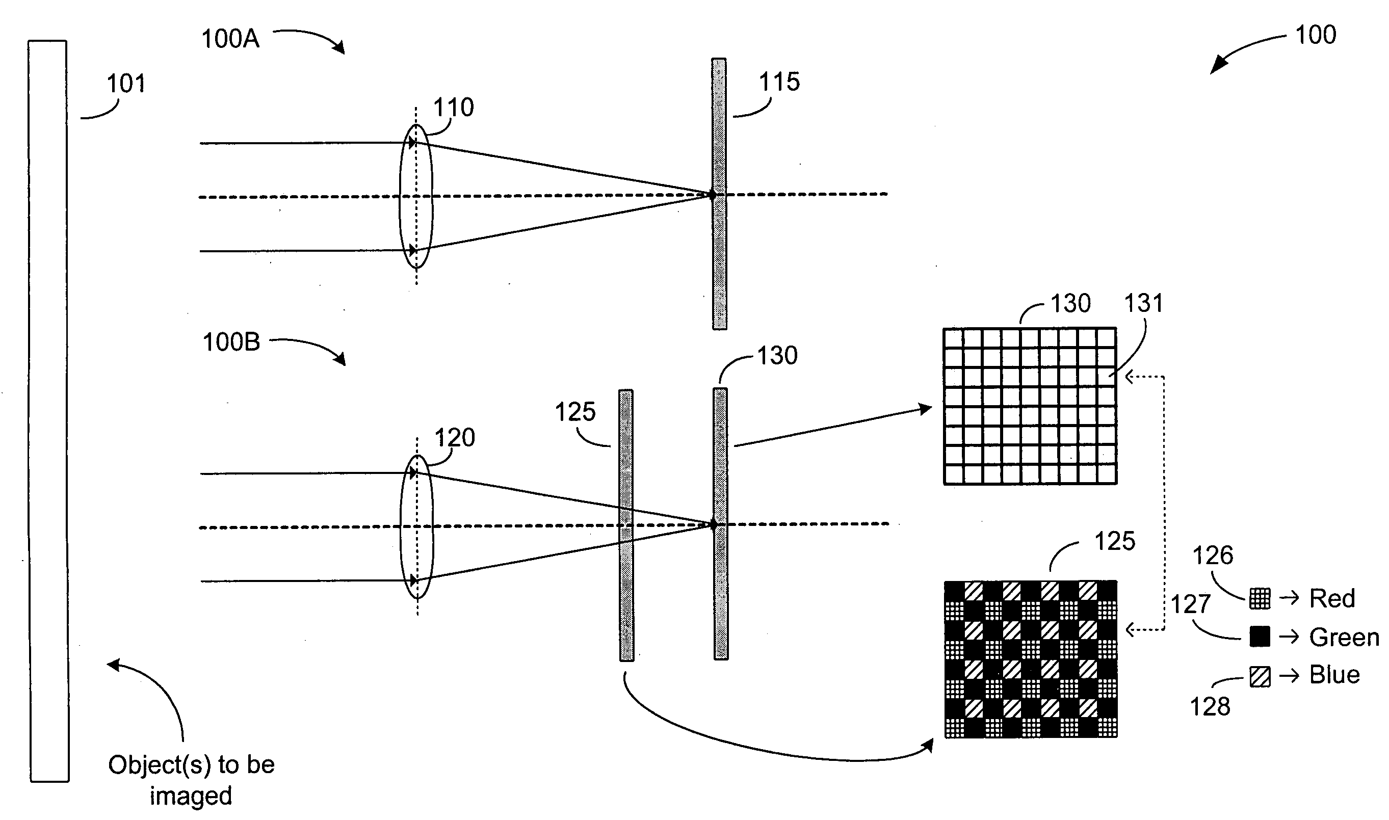
[0021]FIG. 1 shows an exemplary two-lens imaging system 100 that uses a first lens system 100A to obtain luminance information of an object 101 to be imaged, together with a second lens system 100B to obtain chrominance information of the object 101.

[0022] Lens 110 receives a full spectrum of visible light from object 101 and directs this light onto a luminance sensor array ...

first embodiment

[0032] In a first embodiment, the three optical filters 405, 425, and 445 have mosaic patterns that differ from one another. Optical filter 405 is a red-green filter with a mosaic pattern that is different from that of optical filter 425, which is a red-green-blue Bayer filter. Optical filter 445 is yet another variant, having a blue-green mosaic pattern that is different from the mosaic patterns contained in optical filters 405 and 425. The three sets of information obtained from sensors 415, 430, and 440 are combined to generate an image of the object.

[0033] In a second embodiment of FIG. 4, the three optical filters 405, 425, and 445 are similar to one another. For example, all three optical filters are identical Bayer color filters, each of which has as many pixel elements as that contained in an optical filter of a prior-art single-lens system. However, due to super-resolution, the depth of field of the three-lens imaging system 400 becomes significantly superior to that of the...

third embodiment

[0035] In FIG. 4, the three lens systems 400A, 400B, and 400B incorporate off-axis imaging in conjunction with on-axis imaging. One or more of lenses 410, 420, and 435 are configured to provide an optimum modulation transfer function (MTF) at an off-axis location on a corresponding one of sensors 415, 430, and 440. More details of such a system can be obtained from co-pending patent application titled “Imaging systems and methods,” (Russ Gruhlke et al.), which is herein incorporated by reference in its entirety.

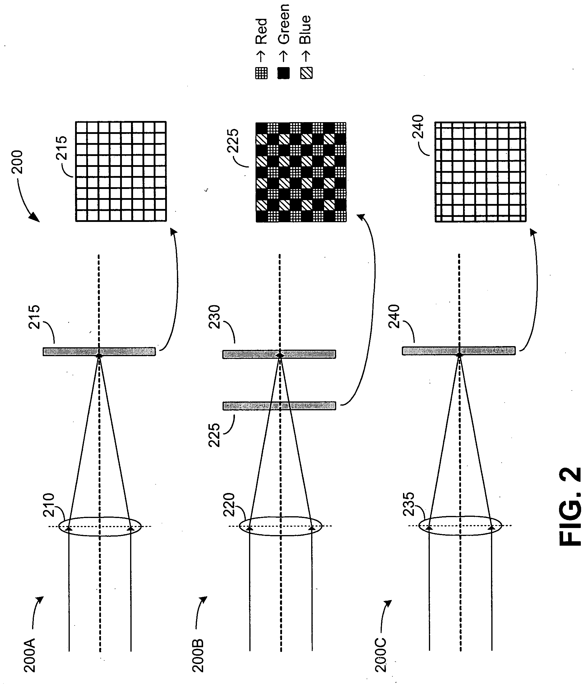
[0036]FIG. 5 shows an exemplary three-lens imaging system 500 that uses three lens systems, 500A, 500B, and 500C to obtain three sets of chrominance information of an object to be imaged (not shown). In a first embodiment, each of the three optical filters 505, 525, and 545 incorporates one or more four-quadrant filters where each of the quadrants is configured to propagate a sub-spectrum of incident light. For example, the first quadrant of four-quadrant filter 505A may be c...


PUM


Abstract

Imaging systems and methods are provided. One exemplary system incorporates multiple lenses that are individually configured to receive visible light from an object to be imaged, and to direct this light upon a corresponding sensor array. Luminance information is then derived from signals generated in one or more of the sensor arrays. When chrominance information is desired, an optical filter is interposed between a lens and the corresponding sensor array. The mosaic pattern contained in the optical filter is tailored to provide advantageous chrominance information. One or more such filters with different mosaic patterns may be employed. The luminance and chrominance information obtained from the sensor arrays are combined to generate an image of the object.

Description

DESCRIPTION OF THE RELATED ART [0001] Image capture devices such as digital cameras, desktop cameras attached to personal computers, and cameras built into mobile telephones, typically have a single lens through which light that is received from an object to be photographed, is directed on to a charge-coupled device (CCD) sensor array, or alternatively, a complementary metal oxide semiconductor (CMOS) sensor array. Because most of these cameras are color cameras, a pixilated color filter is interposed between the lens and the sensor array. The color filter normally contains an array of red, green, and blue filter elements, often configured in a mosaic pattern that is referred to in the industry, as a Bayer pattern. Each element of the color filter, regardless of the color transmitted through the element, is aligned with a sensor element located in the sensor array. Such an alignment enables color pixel information to be captured in the sensor array. This color pixel information is t...

Claims


Application Information

Patent Timeline
Patent Type & Authority Applications(United States)
IPC IPC(8): H04N9/68
CPCH04N9/045H04N25/134H04N23/10H04N23/12
Inventor GRUHIKE, RUSSELL W.SCHROEDER, DALE W.STANBACK, JOHN H.
Owner APTINA IMAGING CORP
Why Eureka
Try Eureka