
Method, network elements, a terminal, a network infrastructure, and a communication system for triggering events

Inactive Publication Date: 2006-06-15
NOKIA CORP
View PDF4 Cites 17 Cited by
  • Summary
  • Abstract
  • Description
  • Claims
  • Application Information

AI Technical Summary

Benefits of technology

[0058] It is an advantage of the present invention that existing lower layer procedures, e.g. link layer procedures, are used to trigger higher layer procedures, e.g. IP layer procedures.
[0059] Thus, it is a further advantage of the embodiments of the present invention that lower layer procedures and higher layer procedures do interwork with each other in an efficient manner.
[0060] With the embodiments of the present invention, with higher layer procedures and lower layer procedures interworking with each other, delays caused by separate procedures are reduced and system performance is improved.
[0061] With the embodiments of the present invention, no excessive higher layer signaling is needed.
[0062] It is another advantage of the present invention that spectrum efficiency is improved.

Problems solved by technology

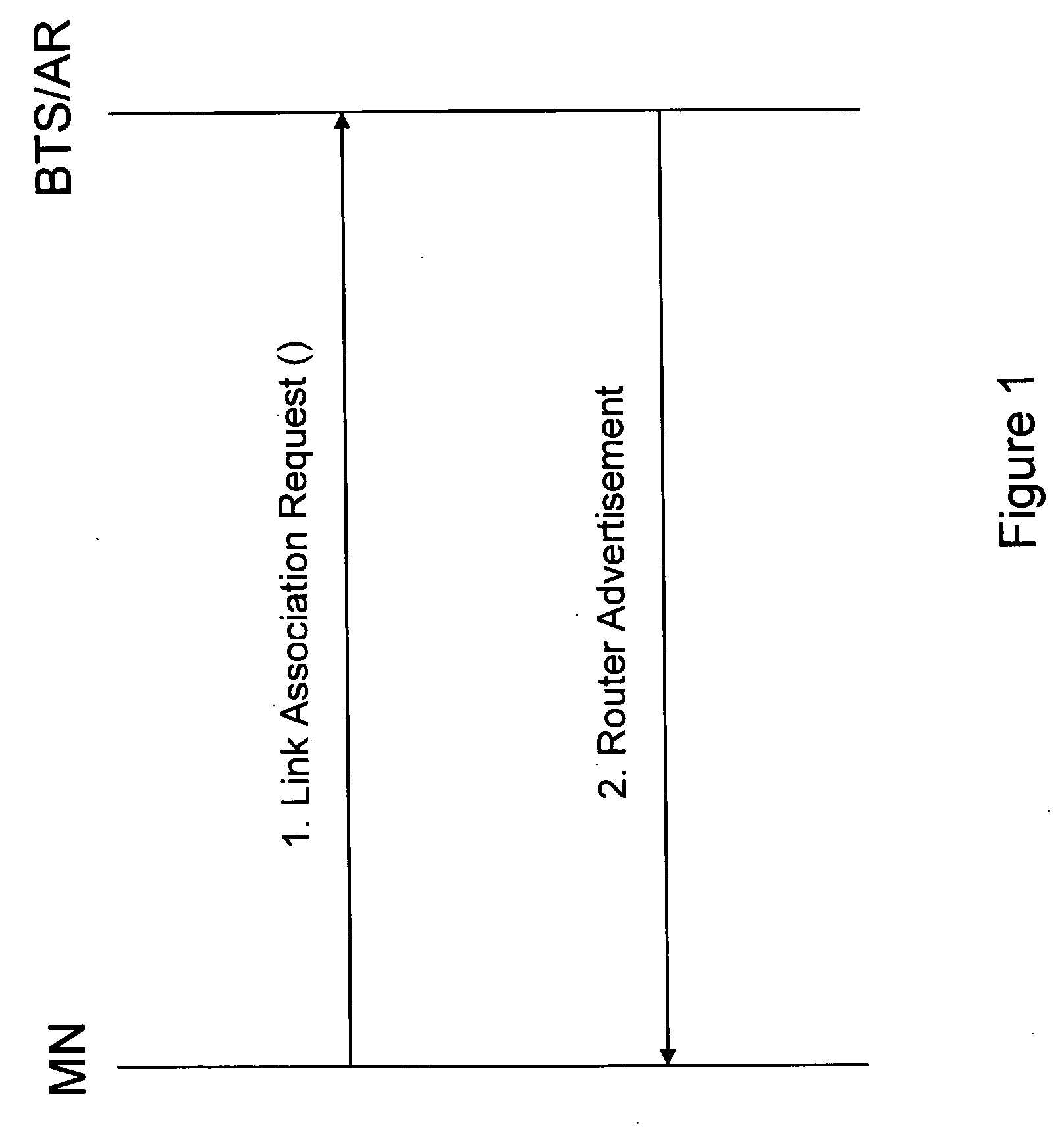
However, when using such fixed network protocols and / or technologies for mobile communications, there may occur a plurality of problems because of these protocols and / or technologies not being specifically designed for the conditions and needs of mobile communications.
However, they are hardly applicable to a system like a wireless network where seamless mobility is vital, handovers occur very often, and maintaining a high spectrum efficiency is also essential.
This basically indicates that the mobile terminal may experience a rather long and possibly unacceptable (in particular, for certain realtime services) delay before it can request and / or configure its IP address after attaching to a wireless system.
Even if the regular prior art procedure described above may be applicable to the terminal power-up procedure where a longer delay is still tolerable (e.g. for non-realtime services), it is not applicable to handover procedures where a seamless communication has to be ensured.
However, the presented procedures have several disadvantages in terms of excessively long delays until network layer configuration is established, low spectrum efficiency due to excessive network layer signaling, and inflexibility.

Method used


Image

  • Method, network elements, a terminal, a network infrastructure, and a communication system for triggering events
  • Method, network elements, a terminal, a network infrastructure, and a communication system for triggering events
  • Method, network elements, a terminal, a network infrastructure, and a communication system for triggering events

Examples


first embodiment

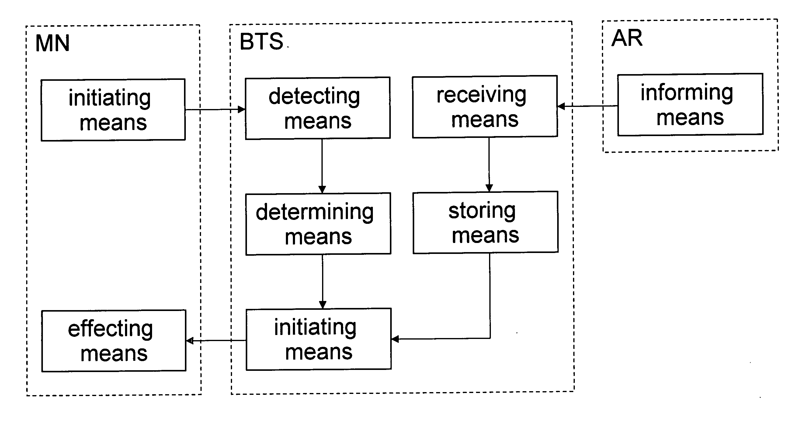
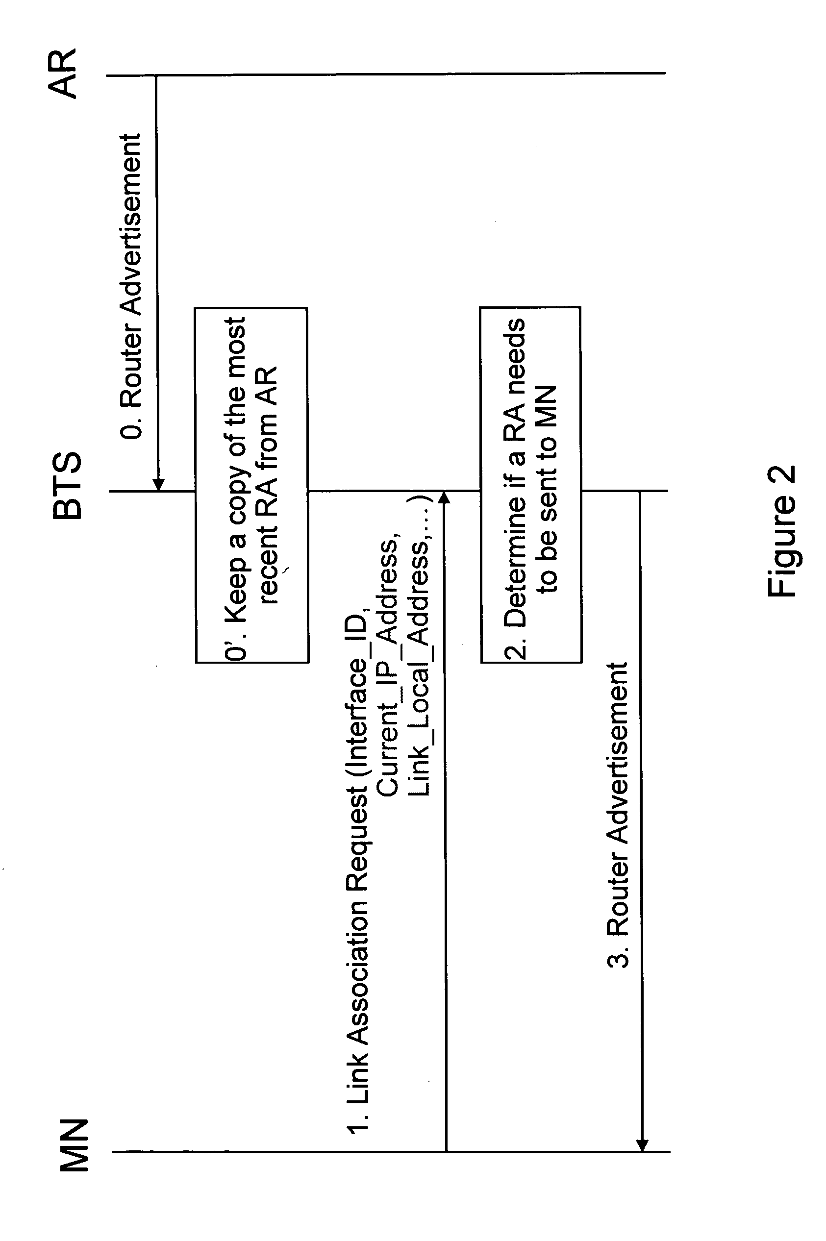
[0079]FIG. 2 depicts a signaling flow chart according to a first embodiment of the present invention. In this figure, the network infrastructure consisting of a base transceiver station BTS and an access router AR is illustrated to be split up. However, it is to be noted that both network elements can also be implemented at the same place and / or in a conjoint infrastructural node.

[0080] The basic idea of the present embodiment is that the base transceiver station representing a first network element determines if a higher layer message needs to be sent based on the presence or the value of one or more parameters carried in a lower layer message. If required, the base transceiver station sends the higher layer message, or in general initiates the higher layer event, on behalf of the access router representing a second network element.

[0081] In step 0 of FIG. 2, the access router AR sends a Router Advertisement message to the base transceiver station. The base transceiver station st...

second embodiment

[0101]FIG. 4 depicts a signaling flow chart according to a second embodiment of the present invention. Thereby, in the implementation according to FIG. 4, the base transceiver station has intelligence to determine the need for a higher layer event or message based on a lower layer event or message.

[0102] This embodiment is somehow similar to the implementation examples presented above. The difference resides in that the base transceiver station BTS requests the access router AR to send a Router Advertisement instead of sending it on behalf of the access router AR. Thus, no storing of respective information on the higher layer event or message and no storing means are needed at the base transceiver station BTS.

[0103] In step 1 of FIG. 4, the mobile node sends a link layer message for requesting a link establishment to first network element, i.e. to the base transceiver station. Upon receiving the respective Link Association Request message, the base transceiver station BTS first de...

third embodiment

[0116]FIG. 6 depicts a signaling flow chart according to a third embodiment of the present invention. Thereby, in the implementation according to FIG. 6, instead of in the base transceiver station, intelligence to determine the necessity for a higher layer event or message based on a lower layer event or message resides in the access router. That is, the base transceiver station is not able to decide on the necessity for a network layer event or message when detecting a lower layer event or message.

[0117] In this case, upon detection of a lower layer event such as upon reception of a Link Association Request message from the mobile node MN (step 1), the base transceiver station BTS in step 2 always sends a request for a higher layer event to the access router AR. In FIG. 6, this request is represented by the RA Request message. The access router AR determines in step 3 if a higher layer event / message such as a Router Advertisement needs to be sent / excited to / at the mobile node righ...


PUM


Abstract

A method, network elements, a terminal, and a system of triggering events in a protocol layer stack of a communication system comprising at least one terminal and a network infrastructure including at least a first network element and a second network element, the method comprising the steps of detecting a terminal-related event of a lower protocol layer at the first network element; initiating a network-related event of a higher protocol layer to be rendered effective at the terminal, wherein the step of initiating further comprises a step of determining a necessity for the higher layer event on the basis of the detected lower layer event, and the step of initiating is effected in case the step of determining yields a necessity for the higher layer event to be triggered.

Description

FIELD OF THE INVENTION [0001] The present invention relates to a method, network elements, a terminal, a network infrastructure, and a communication system for triggering events in a protocol layer stack of a communication system. In particular, the present invention relates to an interworking of link layer procedures and network layer procedures in a communication network environment. BACKGROUND OF THE INVENTION [0002] In recent years, communication technology has widely spread in terms of number of users and amount of use of the telecommunication services by the users. This also led to an increase in the number of different technologies and technological concepts in use. [0003] Thereby, developments have been especially remarkable in mobile communication networks. In this connection, one trend is an increasing usage of communication protocols for wireless communications, that have originally been designed and hitherto been used for fixed networks. The most popular and widely sprea...

Claims


Application Information

Patent Timeline
IPC IPC(8): H04J3/16
CPCH04W36/0011H04W36/0016H04W36/10H04W60/04H04W80/04H04L69/32H04L69/321H04W36/0019
Inventor ZHENG, HAIHONGPURNADI, RENESREEMANTHULA, SRINIVASLE, KHIEMRINNE, MIKKO J.EKLUND, GARL
Owner NOKIA CORP
Learn More