Modulation E-field based control of a non-linear transmitter

a non-linear optical transmitter and modulation e-field technology, applied in the field of system and method control of non-linear optical transmitters, can solve the problems in terms of overall system response, and inability to compensate non-linear impairments such as spm and four-wave mixing, and achieve the effect of accurate synthesis of a desired e-field

Active Publication Date: 2006-06-15
CIENA
View PDF47 Cites 94 Cited by
  • Summary
  • Abstract
  • Description
  • Claims
  • Application Information

AI Technical Summary

Benefits of technology

[0030] An advantage of the present invention is that accurate synthesis of a desired E

Problems solved by technology

While this approach is satisfactory for compensating linear distortions (such as chromatic dispersion, and receiver squaring effects) it cannot compensate non-linear impairments such as SPM and four-wave mixing.
Quite apart from the limitations inherent to analog filter circuits, all of which are well known, compensation of non-linear distortions is complicated by the fact that all real electro-optical devices (i.e. lasers, E/O converters etc.) exhibit a response in both phase and amplitude to changes in drive voltage (or current).
Further complicating this situation is that the overall system response, in terms of changes in the output optical E-field (amplitude and/or phase) due to changes in drive signal voltage (or current) tends to be highly non-linear.
As a result, the prior art techniques for compensating linear distortions (such as chromatic dispersion) by applying a predistortion function F[ ] to the drive signals S(t) typically results in compounding the effects of system non-linearities.
This is an operational feature which is simply not possible in prior art transmitters.
In addition to the inherent

Method used


Image

  • Modulation E-field based control of a non-linear transmitter
  • Modulation E-field based control of a non-linear transmitter
  • Modulation E-field based control of a non-linear transmitter

Examples


Embodiment Construction

[0041] The present invention provides methods and apparatus for controlling a non-linear optical transmitter to accurately generate a desired optical E-field at the E / O converter output. Embodiments of the invention are described below, by way of example only, with reference to FIGS. 4-8.

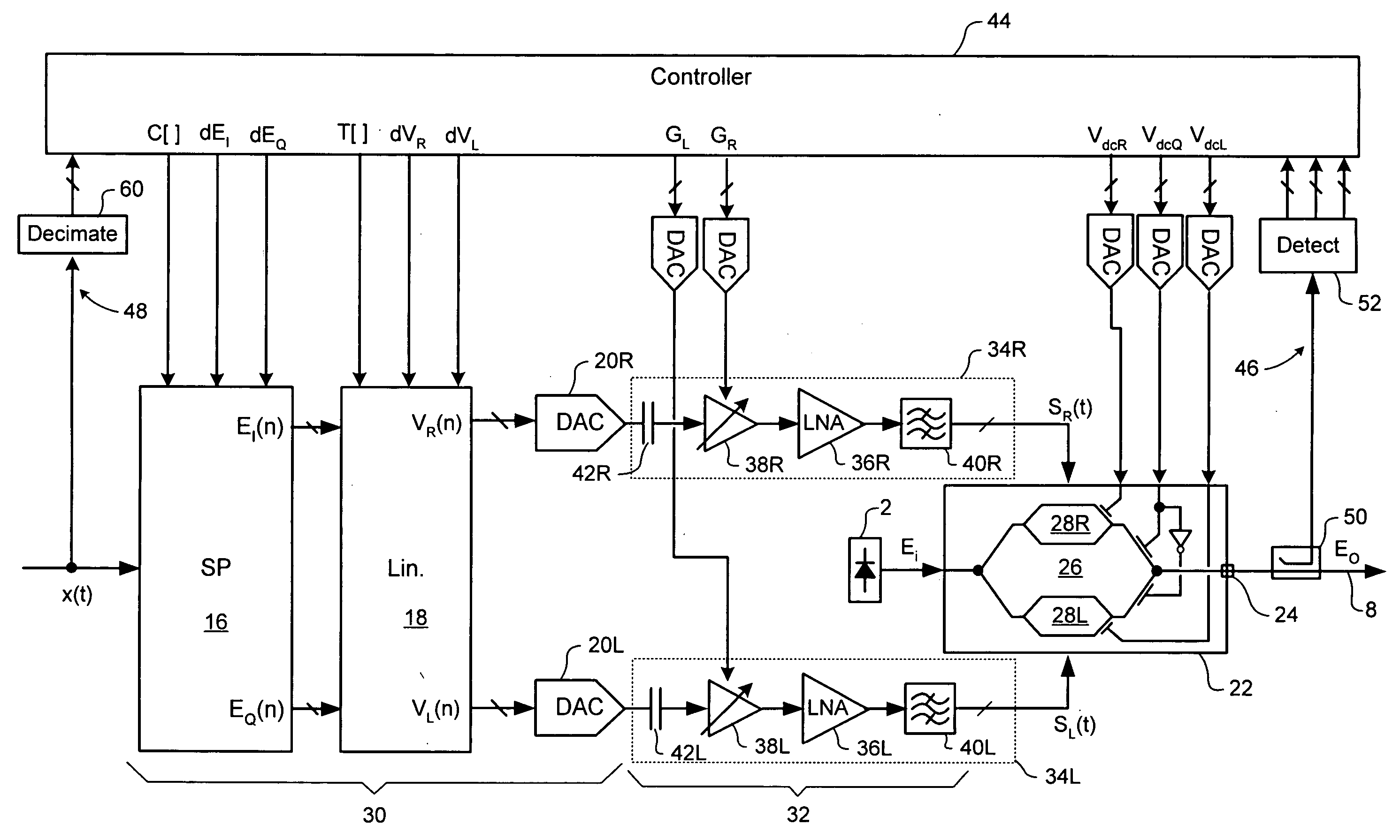
[0042]FIG. 4 is a block diagram schematically illustrating a control system in accordance with the present invention, for controlling a flexible non-linear optical transmitter of the type described above with reference to FIG. 3.

[0043] For the purposes of the present invention, it is useful to consider the transmitter as comprising a high speed “signal path” between the signal processor 16 and the output 24 of the complex E / O converter 22. This signal path comprises a high speed, multi-bit digital stage 30 cascaded with an analog radio-frequency (RF) stage 32, which, in turn, drives the complex E / O converter 22. As shown in FIG. 3a and in more detail in FIG. 4, the multi-bit digital stage 30 inclu...


PUM


Abstract

In a method of synthesizing an optical signal, a multi-bit digital representation of a desired optical E-field is generated. The multi-bit digital representation has a resolution of N1-bits, where N1 is an integer greater than 2. At least two analog drive signals are synthesized based on the multi-bit digital representation. Each analog drive signal exhibits excursions between 2M discrete states (i.e. has a resolution of M-bits), where M is an integer greater than 2. An electrical-to-optical (E/O) converter is driven using the analog drive signals to generate an output optical E-field at an output of the E/O converter. An error is detected between the output optical E-field and the desired complex E-field waveform, and at least one parameter adjusted so as to minimize the detected error.

Description

CROSS-REFERENCE TO RELATED APPLICATIONS [0001] This is the first application filed for the present invention. MICROFICHE APPENDIX [0002] Not Applicable. TECHNICAL FIELD [0003] The present invention relates to optical signal transmitters for optical communications systems, and in particular to a system and methods for controlling a non-linear optical transmitter. BACKGROUND OF THE INVENTION [0004] For the purposes of understanding the present invention, it is useful to consider a representation of the total optical E-field E(t) as a vector confined to a plane and emanating from a fixed origin, where the length of the vector gives the amplitude of the E-field at any instant (t), and the direction of the vector gives the phase of the field at any instant (t). Within this construction, we consider two basis sets. The first basis set is a Cartesian coordinate system centered on the E-field origin. In this Cartesian representation, the total E-field E(t) is decomposed along the orthogonal...

Claims


Application Information

Patent Timeline
IPC IPC(8): H04B10/04
CPCH04B10/505H04B10/5053H04B10/5055H04B10/50572H04B10/50575H04B10/58
Inventor ROBERTS, KIMHARLEY, JAMES
Owner CIENA
Why Eureka
Try Eureka